 |
|||
|
|
|||
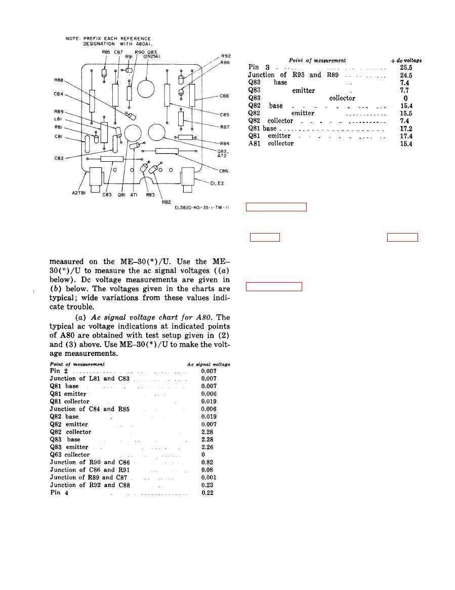
|
|
|||
| ||||||||||
|
|  TM 11-5820-401-35-1/NAVELEX 0967-432-3020
ground). Use the TS-352B/U to make the dc volt-
age measurements.
a. Troubleshooting.
(1) To test the C-2299/VRC before trouble-
shooting and after repair, use procedures given in
(2) Use TS-352B/U to make continuity and
resistance measurements of the C-2299/VRC
board assembly A80A1, parts location; latest version.
b. Repair. Repair parts for the C-2299/VRC
and parts location illustrations are provided in
appendix C. Replacement of microphone ampli-
fier module A80 and other parts are explained in
3-12. Depot Overhaul Standards
Performance Tests
Tests on repaired equipment are designed to
measure the performance capability of the equip-
ment. Equipment that is returned to stock should
meet the standards given in the tests.
NOTE
The depot overhaul standards (c be-
low) should not be used to test the per-
formance of new equipment; that is,
equipment that has not been repaired or
rebuilt. Such equipment should be tested
for conformance with the electrical and
operational tests cited in MIL-C-55126-
(EL) under which the equipment was
manufactured including any waivers
and/or changes to the specification
which were imposed upon or granted to
the particular manufacturer of the equip-
ment. For such information, address
correspondence to Commander, US Army
(b) Dc voltage chart for A80. The typical
Electronics Command, ATTN: AMSEL-
dc voltage indications are indicated points of A80
BE-EC, Fort Monmouth, N.J. 07703.
are obtained with PP-1104/G adjusted to 25.5
volts and connected to pins 3 (+) and 1 (negative
a. Applicable References.
|
|
Privacy Statement - Press Release - Copyright Information. - Contact Us |
