 |
|||
|
|
|||
|
Page Title:
Isolating Troubles in Module A22 |
|
||
| ||||||||||
|
|  (b) DC voltage chart.
(4) After replacing a faulty part, re-
p e a t the procedures given in
d above.
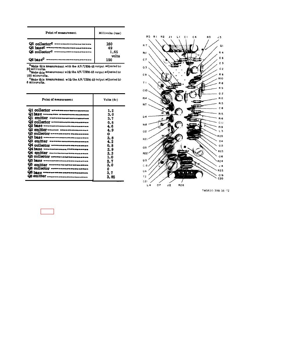
Figure 73. Module A21, parts location.
(b) Tuning knobs for 30.00 mc.
a. Preparation.
(c) Function switch at ON.
(1) Prepare the following test equip-
b. Speech Amplifier Limiter Distortion
ment:
Test.
(1) Connect TS-382F/U betweenpins 3
(b) Multimeter ME-26B/U.
and 4 of A22J1. Connect the ME-
(c) Spectrum Analyzer TS-723A/U.
30A/U across the TS-382F/U out-
(d) Handset H-138/U.
put.
(2) Set TS-382F/U for an output fre-
(f) Voltmeter, Meter ME-30A/U.
quency of 500 cps. Adjust the
(2) Connect the AN/URM-43A to ANT
TS-382F/U for a 1-millivolt indi-
connector J2.
cation on the ME-30A/U. (Maintain
(3) Remove module A23.
this level for each frequency set-
(4) Connect the H-138/U to an AUDIO
ting.)
connector.
(3) Connect the TS-723A/U between
(5) Set the front panel controls of the
A22J3 and ground. Press the push-
receiver-transmitter as follows:
to-talk switch. Measure the audio
(a) BAND switch at 30-52.
distortion. Repeat the procedure
|
|
Privacy Statement - Press Release - Copyright Information. - Contact Us |
