 |
|||
|
|
|||
|
Page Title:
Isolating Trouble in Module A12 |
|
||
| ||||||||||
|
|  (3) Connect a jumper between pin A
(2) Adjust transformer T1 for a maxi-
and C of A12J1.
mum dc indication on the ME-26B/
(4) Set the front panel controls of the
U.
receiver-transmitter as follows:
(3) Set the output of the AN/URM-48
(a) BAND switch at 30-52.
to 5.20 mc.
(b) Tuning knobs to 30.00 mc.
(4) Adjust transformer T2 for a mini-
(c) Function switch at ON.
mum indication on the ME-26B/U.
(5) Set the output of the AN/URM-48
b. Gain Test.
to 5.60 mc. Adjust T1 until the
(1) Connect the AN/URM-25F between
ME-26B/U indicates +2.8 volts dc.
pin B of A12J1 and ground. Connect
(6) Replace module A12.
t h e 411A and the AN/USM-26
across the AN/URM-25 output.
(2) Adjust the AN/URM-25F frequency
to 5.60 mc and the output level to
10 millivolts, as indicated by the
a. Preparation.
411A.
(1) Prepare the following equipment:
(3) Connect the 411A between A12J2
and ground. The 411A should indi-
cate approximately 100 millivolts.
25F.
(4) If the gain does not meet the stand-
(c) Frequency Meter AN/USM-26.
ards of the procedure given above,
(d) Multimeter ME-26B/U.
proceed to d below.
(e) Module extender.
(5) If the gain meets the standards
(2) Remove A12 and A13. Insert the
given above, proceed to c below.
module extender into the recepta-
Do not disturb the equipment set-
cle for A12. Plug A12 into the mod-
ings.
ule extender.
c. Bandwidth Test.
(1) With the AN/URM-25F adjusted as
in a above, note the output level in-
dicated by the 411A.
(2) Adjust the AN/URM-25F frequency
to 5.25 mc and maintain the output
level at 10 millivolts. Note the in-
dication on 411A.
(3) Adjust the AN/URM-25F frequency
to 6.10 mc and maintain the output
level at 10 millivolts. Note the in-
dication on 411A.
(4) The indication obtained in the pro-
cedure given in (2) and (3) above
should be 6 db less than the re-
sponse indicated in (1) above.
d. Faulty Parts Isolation.
(1) Apply a 5.60 mc, 10-mv signal be-
tween pin B of A12J1 and ground.
Measure the voltages at the points
outlined in the charts in (a) and(b)
below. Compare the normal signals
and the dc voltages listed in the
charts .
Note: Connect a jumper between pins A
and C of A12J1 for the measurements
listed below.
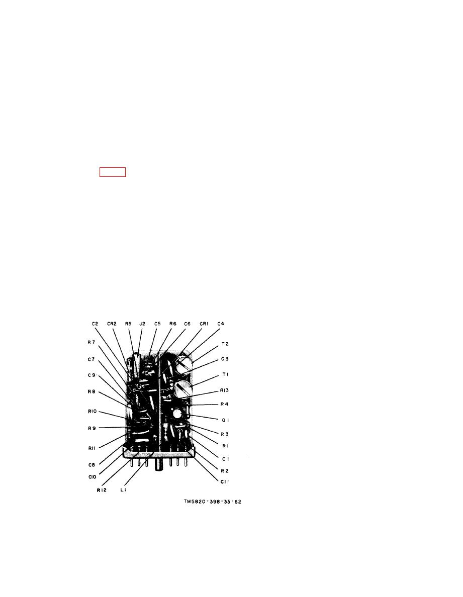
Figure 63. Module A11, parts location.
|
|
Privacy Statement - Press Release - Copyright Information. - Contact Us |
