 |
|||
|
|
|||
|
Page Title:
Isolating Trouble in Module A11 |
|
||
| ||||||||||
|
|  A10J3 ana reconnect the AN/USM-
cedure given in e, f, and g below,
26. The AN/USM-26 should indi-
and repeat the procedures given in
a, b, and c above.
cate 5.6000 mc.
(7) Connect the H-138/U to an AUDIO
(3) Replace A11, A12, and A17. Re-
place the cover on A10.
connector and press the push-to-
e. Preparation for Alignment.
t a l k switch. The AN/USM-26
(1) Prepare the AN/USM-26 and the
should indicate 5.5500 mc.
(8) Set the tuning knobs for 30.00 mc
411A.
and press the push-to-talk switch.
(2) Set the receiver-transmitter con-
trols as follows:
The AN/USM-26 should indicate
(a) BAND switch to 30-52.
5.6000 mc.
(b) Function switch to ON.
(9) Disconnect the AN/USM-26 from
f. 100-KC Interval Oscillator Alignment.
A10J3 and reconnect the 411A.
(1) Set the receiver-transmitter tun-
Press the push-to-talk switch. The
411A should indicate 1.8 volts rms.
ing knobs to 30.50 mc.
(10) Set the tuning knobs for 30.05 mc
(2) Connect the AN/USM-26, in series
and press the push-to-talk switch.
w i t h the 470-ohm resistor, to
The 411A should indicate 1.8 volts
A10J2.
rms.
(3) Adjust T1 until the AN/USM-26
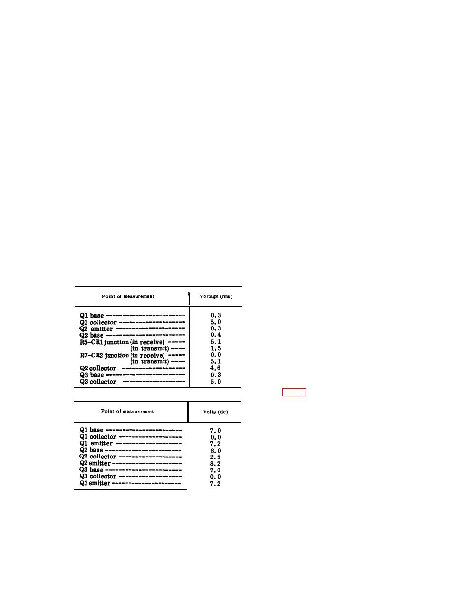
d. Faulty Parts Isolation.
indicates 47.350 mc.
(1) Set the tuning knobs for 30.00 mc.
g. 50-Kc Interval Oscillator Alignment.
-
Measure the voltages at the points
( 1 ) Remove the cover from A10. Re-
outlined below. Compare them with
move A11, A12, A17, A18 fromthe
the normal signal and dc voltages
mother-board.
listed.
(2) Set the tuning knobs to 30.05 mc.
(3) Connect a jumper between pins C
Note: Measure all voltages to ground.
and D of connector J13 (receptacle
(a) Signal voltage chart.
for A17).
(4) Connect the AN/USM-26 to A10J3.
(5) Adjust T2 until the AN/USM-26
indicates 5.6000 mc.
(6) Disconnect the AN/USM-26 and
connect the 411A to A10J3.
(7) Adjust T3 for peak indication on
the 411A.
(8) Replace modules A11, A12, A17
and A18.
(b) Dc voltage chart.
a. Preparation.
(1) Prepare the following equipment:
(d) Multimeter ME-26B/U.
(e) Module extender.
(2) Remove A11. Insert the module
extender into the receptacle for
A11. Remove the cover from A11
and plug A11 into the module ex-
(2) After the replacement of a faulty
t e n d e r . Remove A12 from the
part, perform the alignment pro-
mother board.
|
|
Privacy Statement - Press Release - Copyright Information. - Contact Us |
