 |
|||
|
|
|||
|
|
|||
| ||||||||||
|
|  receiver-transmitter front panel controls
(2) Connect the H-138/U to an AUDIO
as follows:
connector.
(1) Turn the BAND switch to 30-52.
(3) Connect the AN/URM-43A to ANT
(2) Turn the tuning knobs to 30.00 mc.
connector J2.
(3) Turn the function switch to ON.
(4) Place the front panel controls of
e. Alignment Procedure.
the Receiver-Transmitter as fol-
(1) Adjust the AN/URM-48 frequency
lows:
to 30.000 mc and adjust the output
(a) BAND switch at 30-52.
for 10 millivolts between pins A and
(b) Tuning knobs to 30.00 mc.
B of A5J1.
(c) Function switch at ON.
(2) Connect the 411A between A21J3
(5) Remove module A7.
and chassis ground.
(6) Connect the output of the AN/URM-
(3) Adjust A5T2 for a peak indication
48 to the input of AN/USM-26. Ad-
on the 411A.
just AN/URM-48 for 30.000 mc, as
(4) Disconnect all connections.
indicated by the AN/USM-26.
(5) Replace the module cover.
(7) Press the push-to-talk switch on
the H-138/U.
b. Gain and Bandwidth Test.
(1) Connect the output of the AN/URM-
48 between pins 1 and 2 of A6J1.
a. Preparation.
(2) Connect the 411A across the AN/
(1) Prepare the following equipment:
URM-48 output. Adjust the AN/
(a) Frequency Meter AN/USM-26.
URM-48 for a 100-millivolt indica-
tion on the 411A. (Note the db indi-
cation.)
(d) Handset H-138/U.
(3) Disconnect the 411A from the AN/
URM-48 and connect it between
Multimeter ME-26B/U.
pins 1 and 2 of S1J1. The 411A
should indicate 22 db more than the
indication obtained in the proce-
dure given in (2) above. (This value,
+22 db, is the stage gain.)
(4) Adjust the AN/URM-48 level to ob-
tain a 0-db indication on the 411A.
I n c r e a s e the AN/URM-48 fre-
quency until the 411A indicates a
3-db decrease.
(6) Connect the AN/URM-48 to the AN/
USM-26 and record the frequency.
Decrease the frequency of the AN/
URM-48 to 30.00 mc.
(7) Connect the AN/URM-48 between
pins 1 and 2 of A6J1.
(8) Decrease the frequency of the AN/
URM-48 until the 411A indicates a
3-db decrease.
(9) Connect the AN/URM-48 to the AN/
USM-26 and record the frequency.
I n c r e a s e the AN/URM-48 fre-
quency to 30.00 mc.
(10) Compute the difference between the
frequencies recorded in the proce-
dure given in (6) and (9) above. The
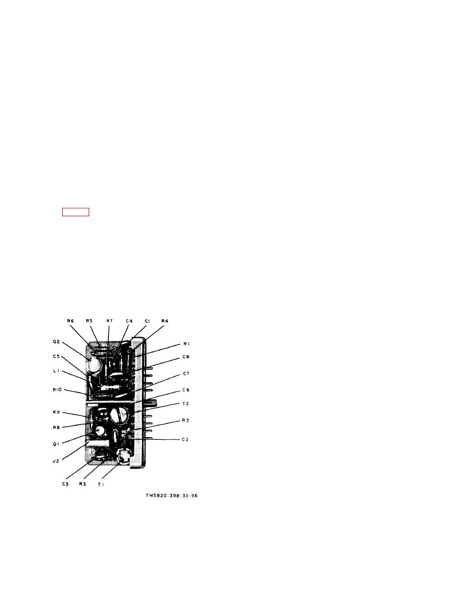
Figure 57. Module A6, parts location.
|
|
Privacy Statement - Press Release - Copyright Information. - Contact Us |
