
TB 9-2320-387-35-6
INSTALLATION PROCEDURES
Section I. SCOPE
This chapter provides instructions for installation of the following C4ISR equipment:
Single Channel Ground and Airborne Radio System (SINCGARS)
Defense Advanced Global Positioning System Receiver (DAGR)
Vehicular Intercommunications Set (VIS)
Force XXI Battle Command, Brigade-and-Below (FBCB2)
Blue Force Tracking (BFT)
Enhanced Position Location Reporting System (EPLRS)
Perform the steps in this chapter when installing SINCGARS, DAGR, VIS, FBCB2, BFT, and EPLRS.
When installing C4ISR equipment, be sure to read and follow instructions and illustrations carefully.
Section II. INTEGRATED RACK INSTALLATION
NOTE
Mounting holes may already exist in tunnel insulation.
If mounting holes exist, skip to step 2-18.
Ensure existing rivet heads in tunnel floor are centered in the
holes when finished drilling.
Locate holes from support bracket, not front of insulation.
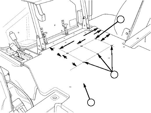
2-1. Locate, mark, and drill three 0.391-in. holes (1) in tunnel insulation (3).
2-2. Locate, mark, and drill three 0.531-in. holes (2) in tunnel insulation (3).
1
25
.68 11.
5
15
6.7
5
2.7
0
7.0
2
~
3
Figure 5-1.