 |
|||
|
|
|||
|
Page Title:
Section XXVII. PAN AND TILT MODULE (PTM) CONTROL ASSEMBLY, CONTROL CABLE ASSEMBLY, AND DCM/PTM INTERCONNECT CABLE INSTALLATIO... |
|
||
| ||||||||||
|
|  TB 9-2320-280-35-5
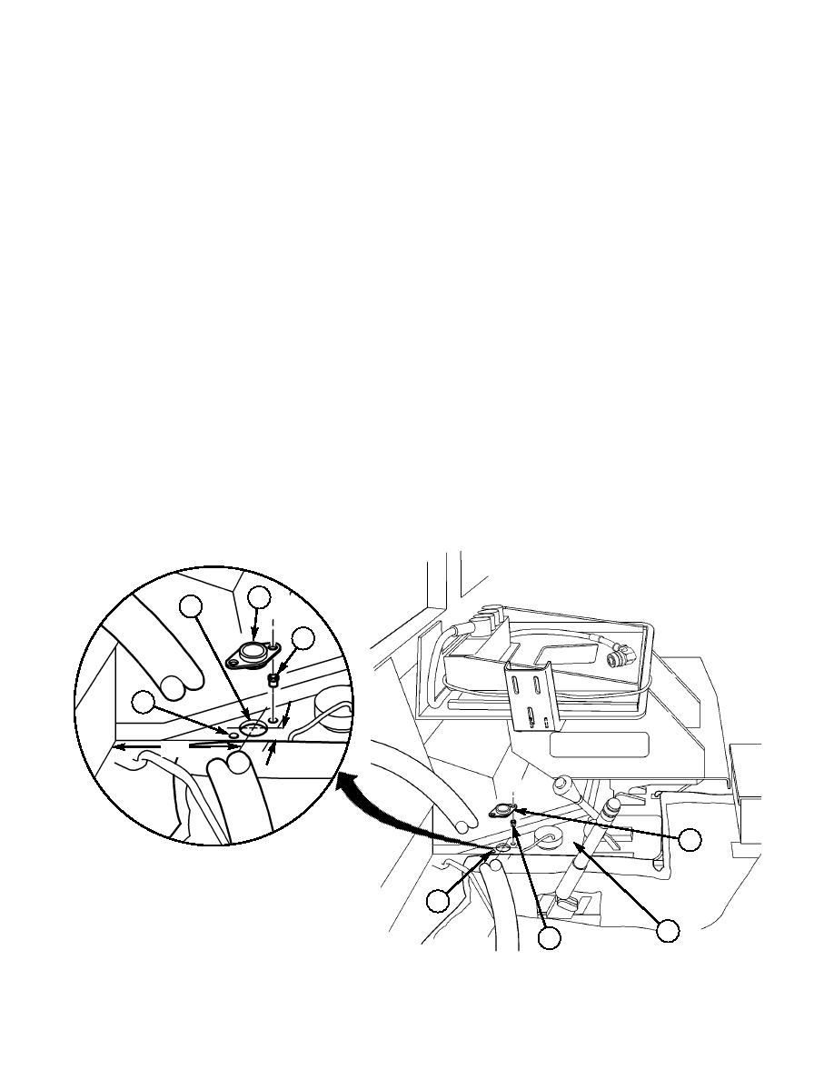
Section XXVII. PAN AND TILT MODULE (PTM) CONTROL ASSEMBLY, CONTROL CABLE
ASSEMBLY, AND DCM/PTM INTERCONNECT CABLE INSTALLATION
27-1. Locate, mark, and drill 1.375-in. hole (1) for control cable seal assembly (2) on tunnel (3).
27-2. Position control cable seal assembly (2) and mark two hole locations (5).
27-3. Drill two 0.391-in. holes in marked locations (5).
27-4. Insert two rivet nuts (4) into tunnel (3).
27-5. Insert DCM connector end of DCM/PTM interconnect cable (6) from transmission compartment
through hole (1) in tunnel (3), through control cable seal assembly (2), and into driver's
compartment.
27-6. For vehicles equipped with FBCB2, route PTM control cable assembly (8) through PTM control
mounting bracket (7).
NOTE
It may be necessary to remove azimuth lock cable adjusting nut to
route cabling.
27-7. Insert two cables (8) and (9) from PTM control mounting bracket (7) through control cable seal
assembly (2).
NOTE
Holes in grommet must be enlarged to allow cables to fit.
27-8. Cut sides of four holes on grommet of control cable seal assembly (2).
27-9. Insert three cables (6), (8), and (9) from PTM control mounting bracket (7) into tunnel hole (1).
27-10. Route three cables (6), (8), and (9) along exhaust pipe (10), body mount (12), and oil filter (11).
Continue routing cables (6), (8), and (9) through engine compartment to A-frame cable guide (14) on
A-frame pillar flange (13) to PTM mount assembly (15).
2
1
4
5
6.50
2.00
2
~
5
3
4
2. CONTROL CABLE SEAL ASSEMBLY 3220908 QTY. 1
4. RIVET NUT 3221004-14 QTY. 2
Figure 5-127.
|
|
Privacy Statement - Press Release - Copyright Information. - Contact Us |
