 |
|||
|
|
|||
|
|
|||
| ||||||||||
|
|  TM 11-6660-204-25
wise direction. This knob is connected to the chart
of gears is used to prevent any backlash between
roller shaft by a set of beveled gears with a ratio
the balancing motor and recorder pen.
(2) The plunger of pen-lifting solenoid L501
of 2 to 1 (figs. 219 and 220).
is connected to the pen-carriage shaft through me-
(6) Three chart guide rods are used in the
chanical parts as shown in figure 2-21. When the
frequency-time recorder, but only two are mova-
solenoid is deenergized, pressure exerted by
ble. The movable intermediate guide rod on the
spring O576 pushes the double-ended bolt against
underside of the frequency-time recorder (fig.
the pen-lifter bracket which rotates the pen-car-
2-19) has a lever mounted on the left side of the
riage shaft slightly, and therby lifts the pen from
rod. When the rod is in its open position (to the
the chart. When the solenoid is energized, the dou-
rear), the lever holds the pen-lifting linkage and
ble-ended bolt is pulled toward the solenoid, The
does not permit the pen-lifting solenoid to lower
pen-pressure nuts then push against the pen-pres-
the recorder pen. The front chart guide rod can be
sure spring which pushes the pen-lifter bracket,
pulled out approximately 1 inch to insert the
The pen-lifter bracket rotates the pen-carriage
chart. The rear chart guide rod is located approxi-
shaft and pushes the pen against the chart roller.
mately halfway between the supply roll and the
The pressure with which the pen is held against
intermediate chart guide rod.
the chart is adjusted by a pen-pressure set nut
and held in place by a locknut.
b. Operation of Recorder Pen,
(3) The pen heater is thermostatically con-
trolled and mounted around the pen barrel (ink
chamber), The heater is operated from 6.3-volt ac
point pen which rides on its carriage above the
source which is supplied through thermostatic
chart roller, The carriage is moved along the pen-
switch S501 and a set of contact bars that run
carriage shaft by the pen-carriage cable which is
parallel and above the carriage shaft. The voltage
connected to a pen-carriage cable drive pulley
is applied from the contact bars to a set of sliding
through two sets of guide pulleys, one at each end
contacts which are connected" to pen heater
of the frequency-time recorder casting, The pulley
HR501. The `thermostatic switch operates the
is attached to the split-gear assembly, which is
heater at temperatures below approximately 0C
driven by balancing motor B501 through a reduc-
(32F. ) Panel lamps 1501 through 1504 are
tion gear assembly. The split-gear assembly con-
lighted by the same 6.3-volt source and provide
sists of two identical gears (sometimes called scis-
sor gears ) that are spring-loaded. The double set
illumination for the recorder scale and chart.
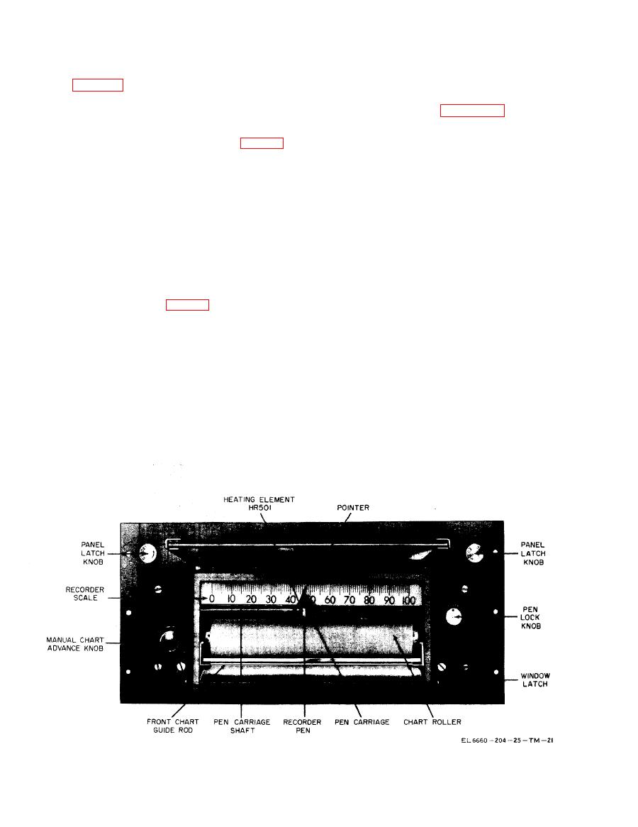
Figure
Frequency-time
recorder,
front
view.
|
|
Privacy Statement - Press Release - Copyright Information. - Contact Us |
