 |
|||
|
|
|||
|
Page Title:
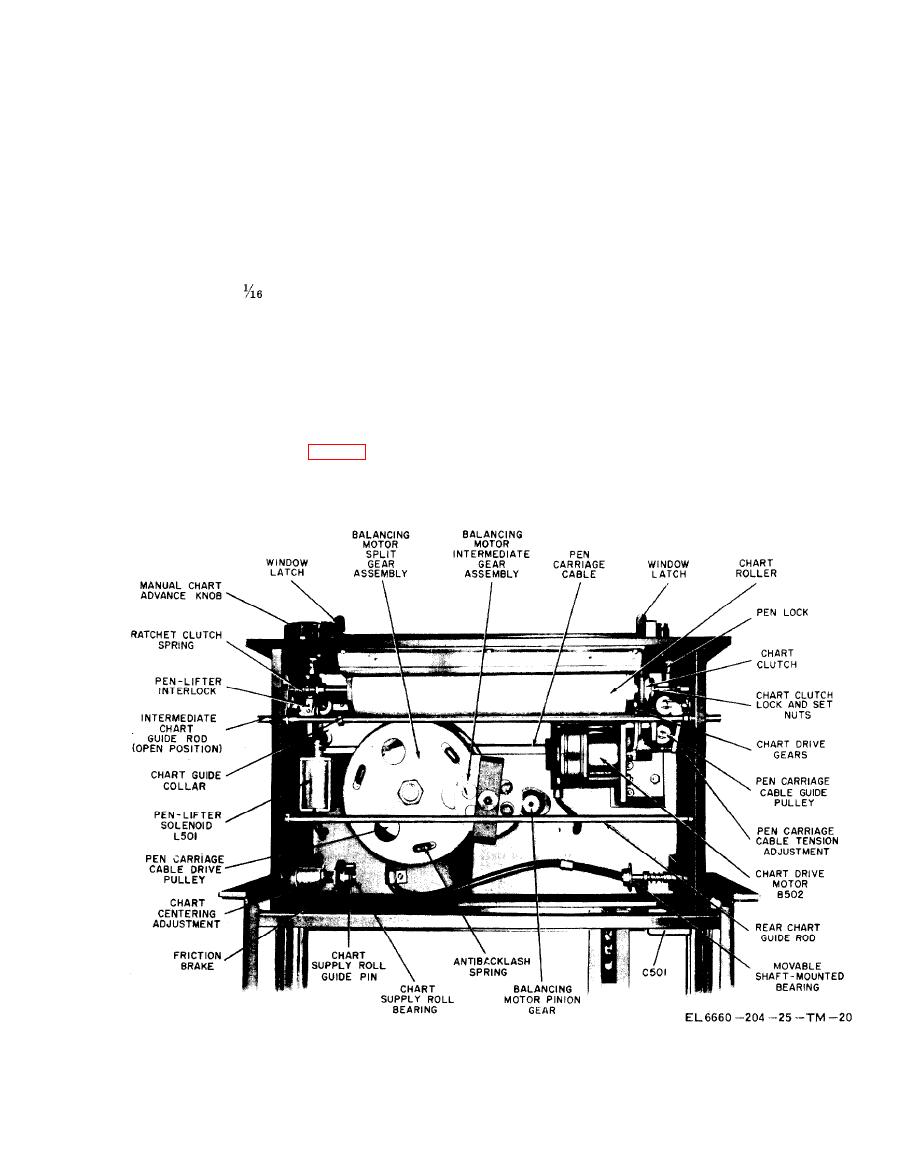
Figure 219. Frequency-time recorder, bottom view showing chart drive details. |
|
||
| ||||||||||
|
|  TM
11-6660-204-25
ceived from the radiosonde receiver in terms of a
left side has a threaded shaft to permit adjust-
calibrated output voltage as indicated on a graph
ment of the chart so it can be aligned with the
recorder. This is done by causing an inking pen to
chart roller which is damped by a spring brass
mark the moving recorder graph chart between
washer to prevent the chart from unwinding eas-
positions fixed by preflight calibration adjust-
ily.
ments and determined by the balancing motor ro-
(3) The chart roller is driven by chart motor
tation and the pen-lifting solenoid operation in
B502 through a reduction gear and a clutch as-
accordance with the received radiosonde signal.
sembly. The perforated edges of the chart coincide
The functions of the recorder areas follows:
with the extrusions of the chart roller, and the
chart is advanced at a constant selective speed.
a. Operation of Chart.
(4) The clutch assembly consists of a black
(1) The chart consists of a paper roll 120
fiber washer, two spring retainers, and three
feet long by 10
inches wide. The vertical
springs mounted between the retainers. The re-
axis of the chart is graduated in l/2-inch intervals,
tainer tabs fit into a slot of the roller shaft. The
and the horizontal axis into 100 equal divisions
clutch assembly is held against a motor-driven
which represent the pulse frequency of the radio-
gear which uses that roller shaft as its axis, but is
sonde signal (normally one division equals 2
not connected to the shaft. As the motor-driven
CPS). The number of feet remaining on the roll is
gear is rotated, the pressure exerted by the three
indicated by the number printed 1/2 inch to the
springs pressing the fiber washer against the flat
right of the zero line.
surface of the gear causes the clutch assembly and
(2) The chart is secured between two shaft-
the chart roller to rotate.
mounted chart roll bearings (fig. 219). The bear-
ing on the right side is spring-loaded to `facilitate
(5) The chart can be advanced manually by
the replacement of the chart, and the one on the
turning the manual chart advance knob in a clock-
Figure 219. Frequency-time recorder, bottom view showing chart drive details.
|
|
Privacy Statement - Press Release - Copyright Information. - Contact Us |
