 |
|||
|
|
|||
|
|
|||
| ||||||||||
|
|  TM 11-5820-873-34
(4) Position front panel in place and secure with
six mounting screws.
six mounting screws.
(7) Reinstall transceiver top cover.
(5) Reinstall transceiver top cover.
4-16. Decoder CCA
4-17. Speaker Driver CCA
a. Removal.
a. Removal.
(1) Remove transceiver top cover.
(1) Remove transceiver top cover.
(2) Remove six mounting screws from front panel
(2) Remove six mounting screws from front panel
to transceiver and position front panel 1A1 for access to
1A1 to transceiver and swing front panel downward.
Speaker Driver 1A1A1.
(3) Disconnect connector 1A1J5 from connector
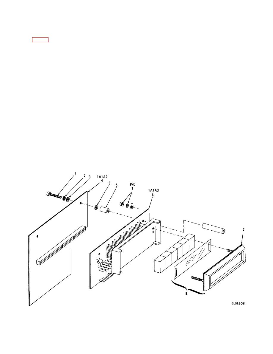
(3) Remove two mounting screws, flat washers
1A1A2J2 on Decoder 1A1A2 (4).
and lock washers from Speaker Driver 1A1A1.
(4) Remove two mounting screws (1), flat washers
(4) Label all wiring connections
(3), and lock washers (2) from Decoder 1A1A2 (4) and
(5) Unsolder wires and remove Speaker Driver
remove Decoder.
Board 1A1A1.
(5) Remove two loose spacers (5) between decoder
b. Replacement.
1A1A2 (4) and display 1A1A3 (6).
b. Replacement.
CAUTION
CAUTION
Component side of Speaker Driver Board
Decoder connector 1A1A2J2 should be
should face the front of the transceiver.
facing to the top and rear of transceiver.
(1) Make proper wiring connections.
(2) Position Speaker Driver Board 1A1A1 in place
(1) Position two spacers (5) in place between
and secure with two mounting screws, flat washers and
Display Assembly (6) and Decoder (4).
lock washers.
(2) Position Decoder (4) in place and secure with
(3) Position Front Panel 1A1 in place and secure
two mounting screws (1), flat washers (3) and lock
with six mounting screws.
washers (2).
(4) Reinstall transceiver top cover.
(3) Connect connector 1A1J5 to 1A1A2P2.
Figure 4-6. Display Assembly
4-38
|
|
Privacy Statement - Press Release - Copyright Information. - Contact Us |
