 |
|||
|
|
|||
|
|
|||
| ||||||||||
|
|  TM 11-5820-873-34
(5) Remove two loose spacers (5) between
NOTE
Decoder 1A1A2 (4) and Display 1A1A3 (6).
When inserting circuit card assemblies in
(6) Remove two mounting nuts, flat washers, and
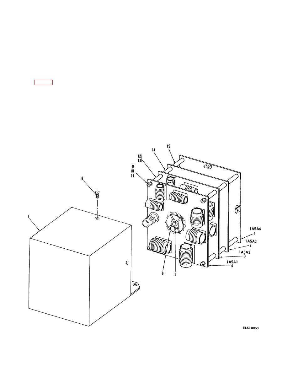
shield box (7) relays 1A5A4K1 and 1A5A4K2
lock washers (7) from Display 1A1A3 (6) and remove
must match up with long side of shield box.
Display.
(4) Position circuit card assemblies in place and
(7) Remove lens and bezel (8) from front of Front
reinstall four mounting screws (8)
Panel.
(5) Reinstall Filter module 1A5 following Filter
b. Replacement.
Module replacement procedures
(1) Position bezel and lens (8) in place.
4-15. Display CCA
(2) Position Display 1A1A3 (6) in place and
secure with two mounting nuts, flat washers, and lock
a. Removal.
washers (P/O 7).
(1) Remove transceiver top cover
(3) Position two spacers (5) in place between
(2) Remove six mounting screws from front panel
Display 1A1A3 (6) and Decoder 1A1A2 (4)
1A1 to transceiver and swing front panel downward.
(4) Position Decoder 1A1A2 (4) in place and
(3) Disconnect connector 1A1J5 from connector
secure with two mounting screws (1), flat washers (3), and
1A1A2J2 on Decoder 1A1A2 (4).
lock washers (2).
(4) Remove two mounting screws (1), flat washers
(5) Connect connector 1A1J5 to connector
(3) and lock washers (2) from Decoder 1A1A2 (4) and
1A1A2J2.
remove Decoder 1A1A2.
(6) Position front panel m place and secure with
Figure 4-5. Filter Module Circuit Cards
4-37
|
|
Privacy Statement - Press Release - Copyright Information. - Contact Us |
