 |
|||
|
|
|||
|
Page Title:
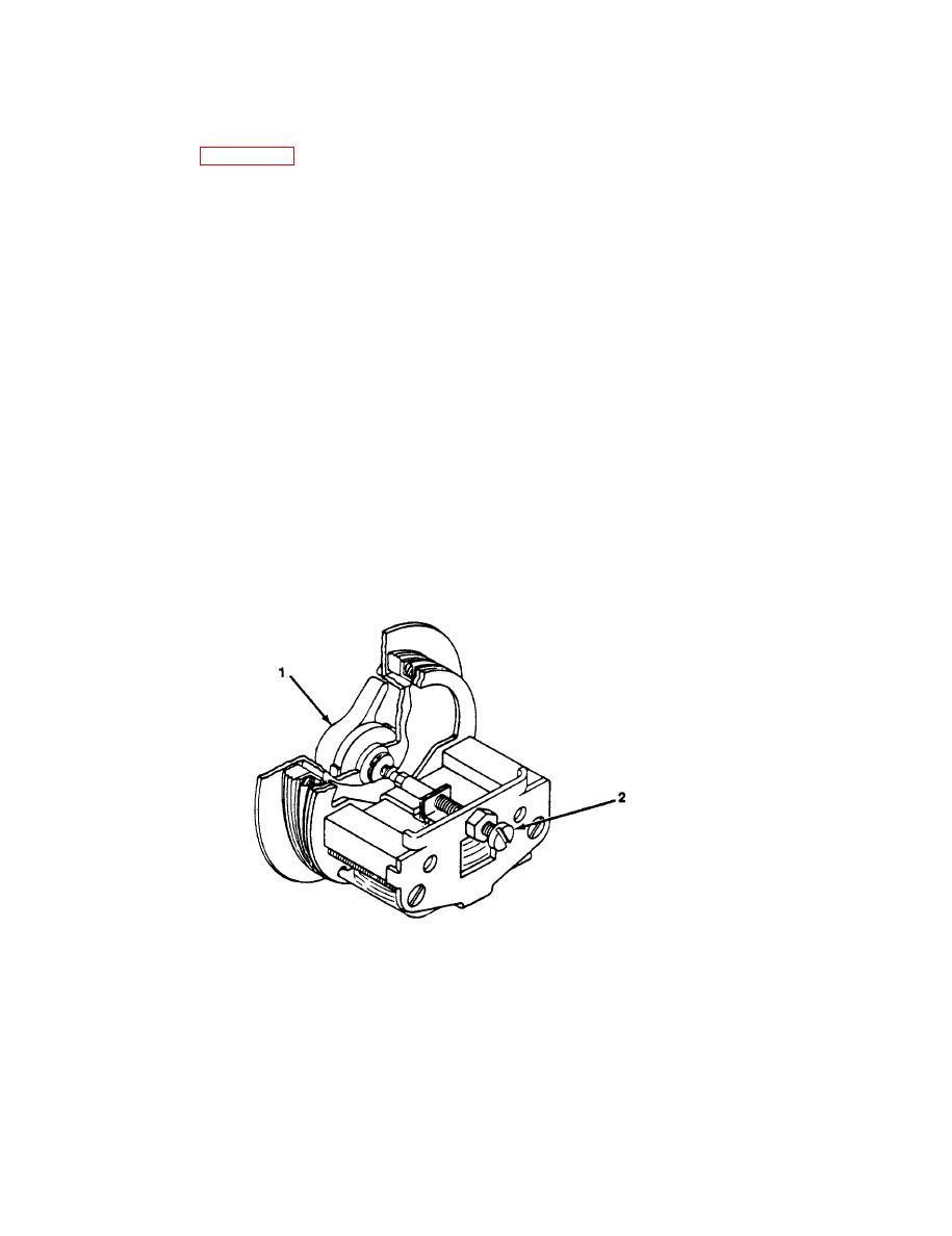
Figure 2-9. Buzzer Adjustment (DS1O1 or DS201). |
|
||
| ||||||||||
|
|  TM 11-5820-477-30
2-11. Buzzer Assembly DS101 or DS201 (cont)
NOTE
Two persons are required for buzzer assembly adjustment.
(1) Release clamp on each side of control unit and slide chassis out of case.
(2) Set BUZZER VOLUME control (1) to midrange position.
(3) Connect control unit to another control unit using field wire.
(4) Press RINGER button on second control unit.
(5) Insert screwdriver into BUZZER ADJUSTMENT hole on rear of chassis.
(6) Adjust buzzer adjustment screw (2) until buzzer can be heard at a distance of 15 feet.
(7) Set BUZZER VOLUME control (1) to OFF.
(8) Press RINGER button on second control unit. No sound should be heard from buzzer assembly.
(9) Slide chassis into case and secure with clamps.
4859-010
Figure 2-9. Buzzer Adjustment (DS1O1 or DS201).
2-28
|
|
Privacy Statement - Press Release - Copyright Information. - Contact Us |
