 |
|||
|
|
|||
|
Page Title:
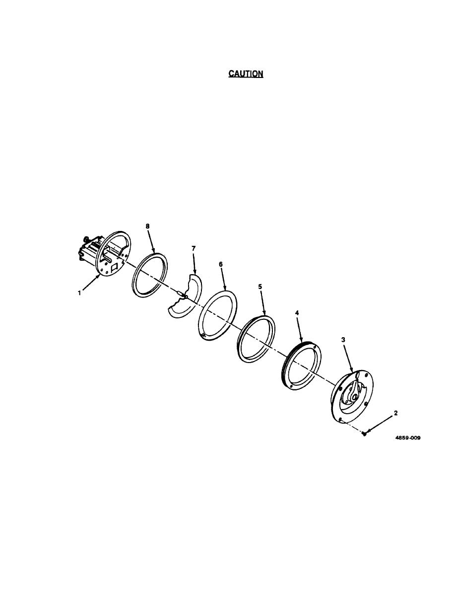
Figure 2-8. Buzzer Assembly DS1O1 or DS201, Replacement. |
|
||
| ||||||||||
|
|  TM 11-5820-477-30
(4) Position cover assembly (3) on front panel over ring nut (4) and secure with four flathead screws (2).
Do not use a soldering gun; damaging voltages can be induced in the components. Use
a pencil-type soldering iron with a 25-watt maximum capacity. If only at-operated iron is
available, use an isolating transformer.
(5) Solder tagged wires to proper terminals on buzzer assembly (1).
(6) Slide chassis into case and secure with clamps.
Figure 2-8. Buzzer Assembly DS1O1 or DS201, Replacement.
2-27
|
|
Privacy Statement - Press Release - Copyright Information. - Contact Us |
