 |
|||
|
|
|||
|
|
|||
| ||||||||||
|
|  TM 11-5820-401-35-1/NAVELEX 0967-432-3020
(a) Turn on and adjust the output of the
(1) Repair standards. Applicable procedures
PP-1104/G to 22 volts.
of the depots performing the test and general
(b) Connect the AN/URM-127 ((1) (d)
standards for repaired electronic equipment given
above) to terminals D and A of test cable No. 1
in TB SIG 355-1, TB SIG 355-2, and TB SIG
connected to J703.
355-3 form a part of the requirement for testing
(c) Adjust the output of AN/URM-127
the C-2299/VRC.
for 500 Hz at 0.007 volt.
(2) Modification work orders. Perform all
(d) Measure A80 output across 150-ohm
modification work orders (MWO's) applicable to
resistor connected to J701 as follows:
the C-2299/VRC before making the tests of the
1. Connect TS-723B/U METER ter-
C-2299/VRC. DA Pam 3107 lists all current
minals across the resistor. The signal voltage
MWO's.
should be 0.22 volt 2 db.
b. Test Equipment and Materials Required.
2. Connect TS-723B/U AF INPUT ter-
The required items are listed in paragraph 3-9.
minals across the resistor. The signal distortion
should be less than 2 percent.
c. Depot Overhaul Standards.
(e) Change AN/URM-127 output fre-
quency to 3,000 Hz at 0.007 volt and repeat
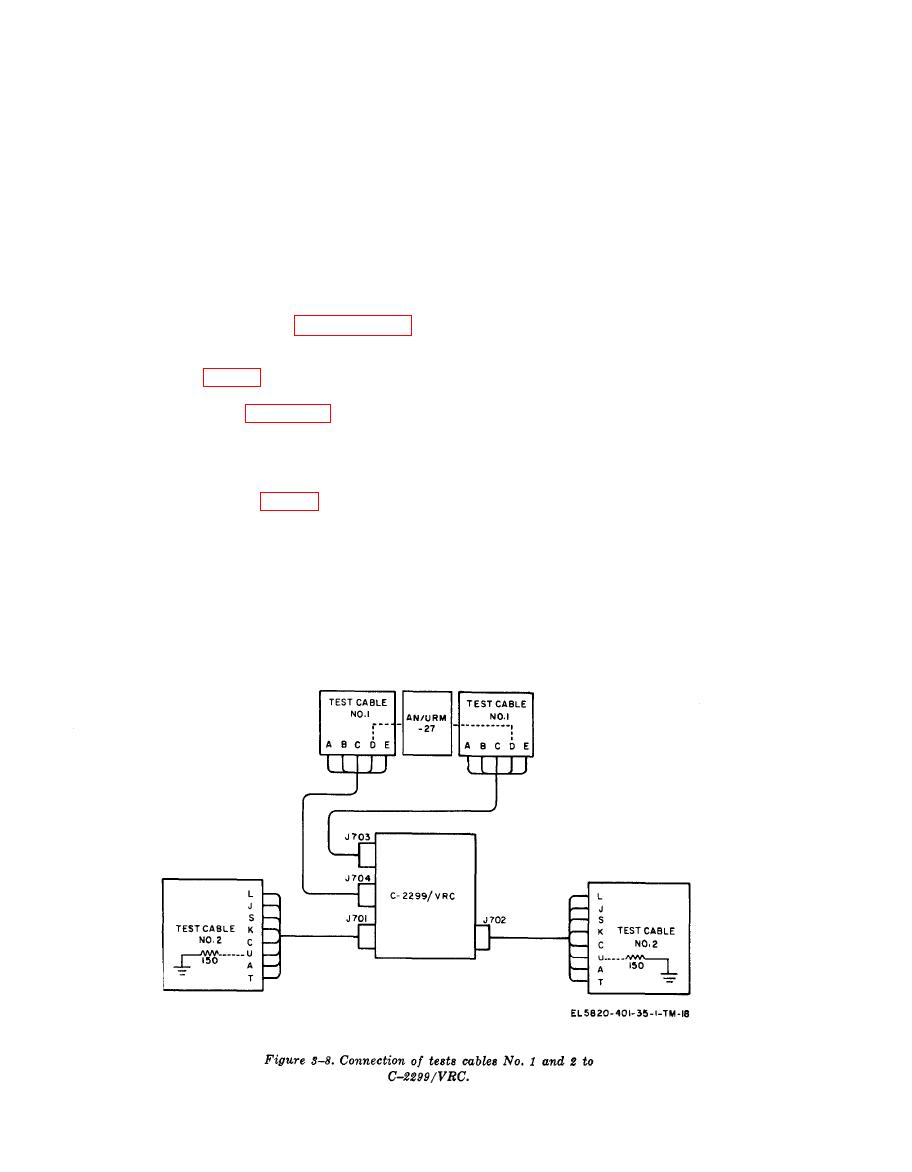
(a) Connect test cables No. 1 and 2 to
measurement in (d) above.
C-2299/VRC as shown in figure 3-8.
(f) Change AN/URM-127 output fre-
(b) Connect a 150-ohm resistor to ter-
quency to 1,000 Hz at 0.007 volt and repeat meas-
minals U and A of each test cable No. 2,
urements in (d) above.
(c) Turn off the PP-1104/G and connect
(g) Adjust the output voltage of PP-
its output to terminals C (+) and A (negative,
1104/G to 30.0 volts and repeat measurements
ground) of test cable No. 2 (fig. 3-5) connected
in (d) above.
to J701.
(h) Adjust output voltage of PP-1104/G
(d) Connect a 150-ohm resistor to the out-
to 25.5 volts and repeat measurements in (d)
put of AN/URM-127 and use ME-30(*)/U con-
above.
nected across the resistor to measure the output
(i) Change connection of AN/URM-127
signal level of each test frequency.
to terminals D and A of J704. Repeat voltage
--
(e) Proceed to tests ((2) below).
measurement in (d)1 above.
(2) Audio amplifier performance tests, Set
(j) Remove connection of TS-723B/U
up the equipment as explained in (1) above.
from J701 and connect to 150-ohm resistor con-
|
|
Privacy Statement - Press Release - Copyright Information. - Contact Us |
