 |
|||
|
|
|||
|
|
|||
| ||||||||||
|
|  TM 11-5820-401-35-1/ NAVELEX 0967-432-3020
adjusted to measure resistance (RX1), to make
netted to U and A of J702. Set C-2299/VRC
following circuit continuity measurements. Leave
RAD TRANS switch to position 2. Repeat volt-
test cables connected to C-2299/VRC (fig. 3-8).
age measurement in (d) 1 above.
(k) Turn off PP-1104/G and remove con-
Continuity (0 ohm) should be obtained for each
terminal-to-terminal measurement, except when
nections of PP-1104/G, resistors, and test equip-
150 ohms is indicated. When no switch/position
ment from the test cables.
is given, switches may be set in any position. Be-
(l) Make continuity measurements in (3)
fore proceeding, set C-2299/VRC VOLUME con-
and (4) below.
trol fully counterclockwise.
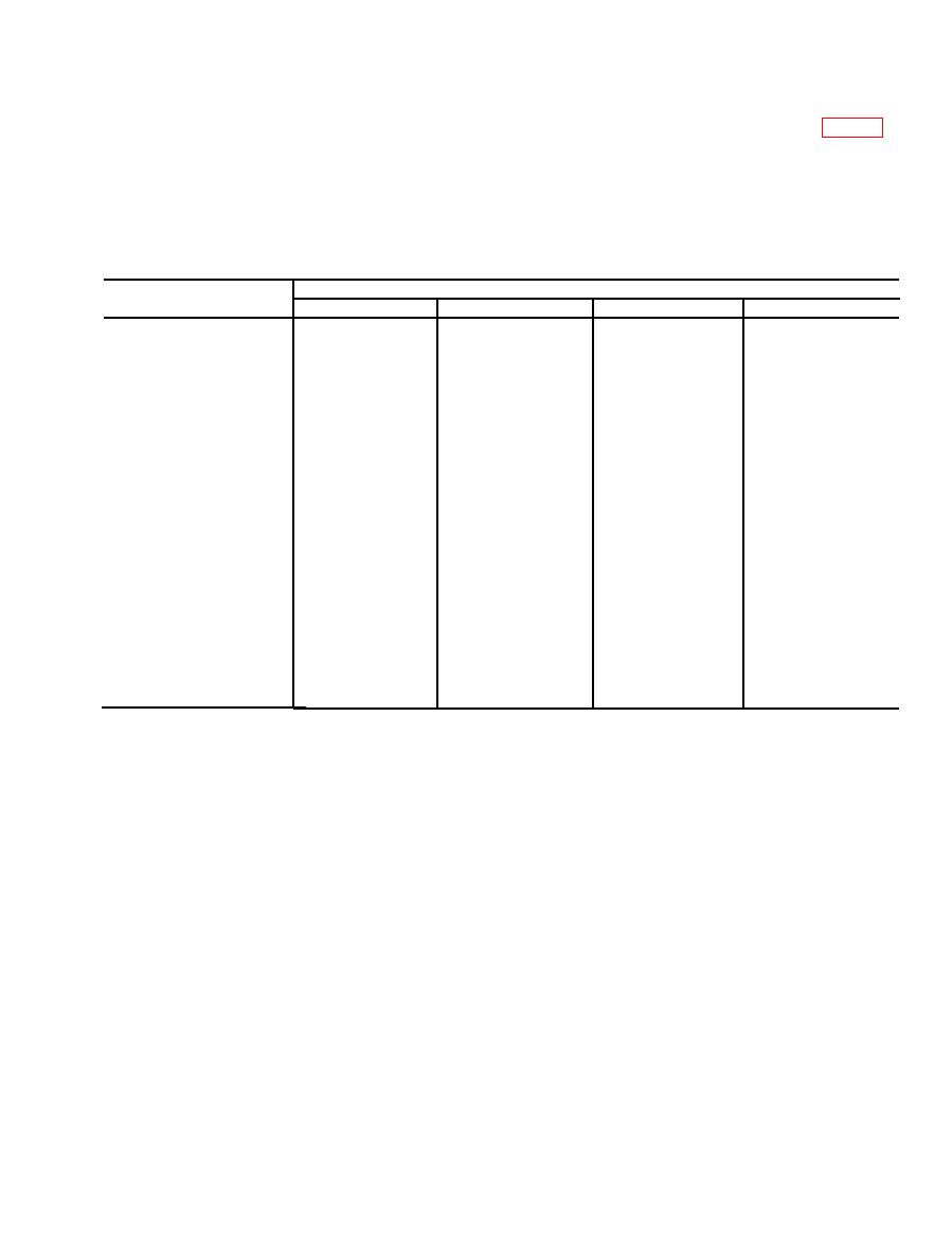
(3) Continuity tests. Use the TS-352B/U,
Receptacle/s/ terminals
J701
J702
Switch/position
J'703
J704
B and E
B
B
B
E
B and E
RAD TRANS : 1
L
C
L
C
J
B
B
J
RAD TRANS : 2
L
C
L
C
B
J
B
J
RETRANS : OFF
L and S
L and S
K and V
K and A
(150 ohms)
K and A
(150 ohms)
RETRANS : ON
S
T
T
S
K
U
K
U
(4) VOLUME control teds.
control from counterclockwise to clockwise posi-
tions.
(a) Connect the TS-352B/U between ter-
(c) The TS-352B/U should indicate no
minals E of J703 and J of J701.
erratic movement during rotation of the control
(b) Adjust the TS-723B/U for on-scale
and should register between 0 and 100,000 ohms
ohms indications while rotating the VOLUME
(10 percent).
3-13
|
|
Privacy Statement - Press Release - Copyright Information. - Contact Us |
