 |
|||
|
|
|||
|
|
|||
| ||||||||||
|
| 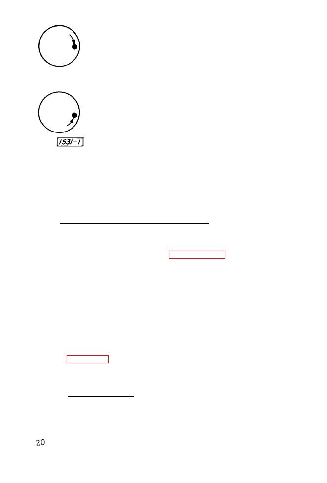 Now, if the flashing rate of the stroboscope is slowed to
1799 flashes per minute, the dot will be illuminated at a
slightly different position each time the disc revolves,
and the dot will appear to move slowly in the direction of
rotation through 360 and arrive back at its original posi-
tion (3 o `clock) one minute later.
A similar movement, but in a direction opposite the ro -
tat ion of the dot, will be observed if the flashing rate of
the stroboscope is increased to 1801 rpm. If desired, the
rate of apparent movement can be speeded up by further
increases or decreases in the stroboscope flashing rate.
When the image is stopped, the flashing rate of the stroboscope
equals the speed of the moving object and, since the flashing rate is
known, the speed of the object is also known. Thus the stroboscope has
a dual purpose of measuring speed and of apparently slowing down or
stopping rapid motion for observation. The practical significance of the
slow -motion effect is that, since it is a true copy of the high-speed motion,
all irregularities (vibration, torsion, chattering, whip) present in the
high -speed motion can be studied.
3.1.2 SINGLE AND MULTIPLE IMAGES.
Single images will occur at the fundamental speed of the object
under observation, and at predictable submultiple of the fundamental
speed. Multiple images will be observed at various speeds above and
below the fundamental speed. Refer to paragraphs 2.8.1 and 2.8.2.
When the Type 1531 Strobotac is used for observation purposes
only, the ability to distinguish between single and multiple images is
usually not necessary. When making speed measurements, however,
the operator must be able to make this distinction. Generally, odd-
shaped (not symmetrical) objects cause little difficult y. Assume, for
example, a fan with only one blade: the single blade will be seen when
a single image occurs, two blades (1800 apart) will be seen when a double
image occurs, three blades (120 0 apart) will be seen when a triple image
occurs, etc.
But when the object is symmetrical in shape (fan with 4 blades, for
example), multiple images cannot always be distinguished from a single
image. This difficult y is easily overcome; simply upset the symmetry
of the object by applying a reference mark with pencil, paint, chalk, tape,
etc. See Figure 3-1.
3-2. CIRCUIT DETAILS.
3.2.1 G E N E R A L .
The Type 1531 Strobotac consists basically of a strobotron, an
oscillator to determine the flashing rate of the strobotron, and a power
|
|
Privacy Statement - Press Release - Copyright Information. - Contact Us |
