 |
|||
|
|
|||
|
Page Title:
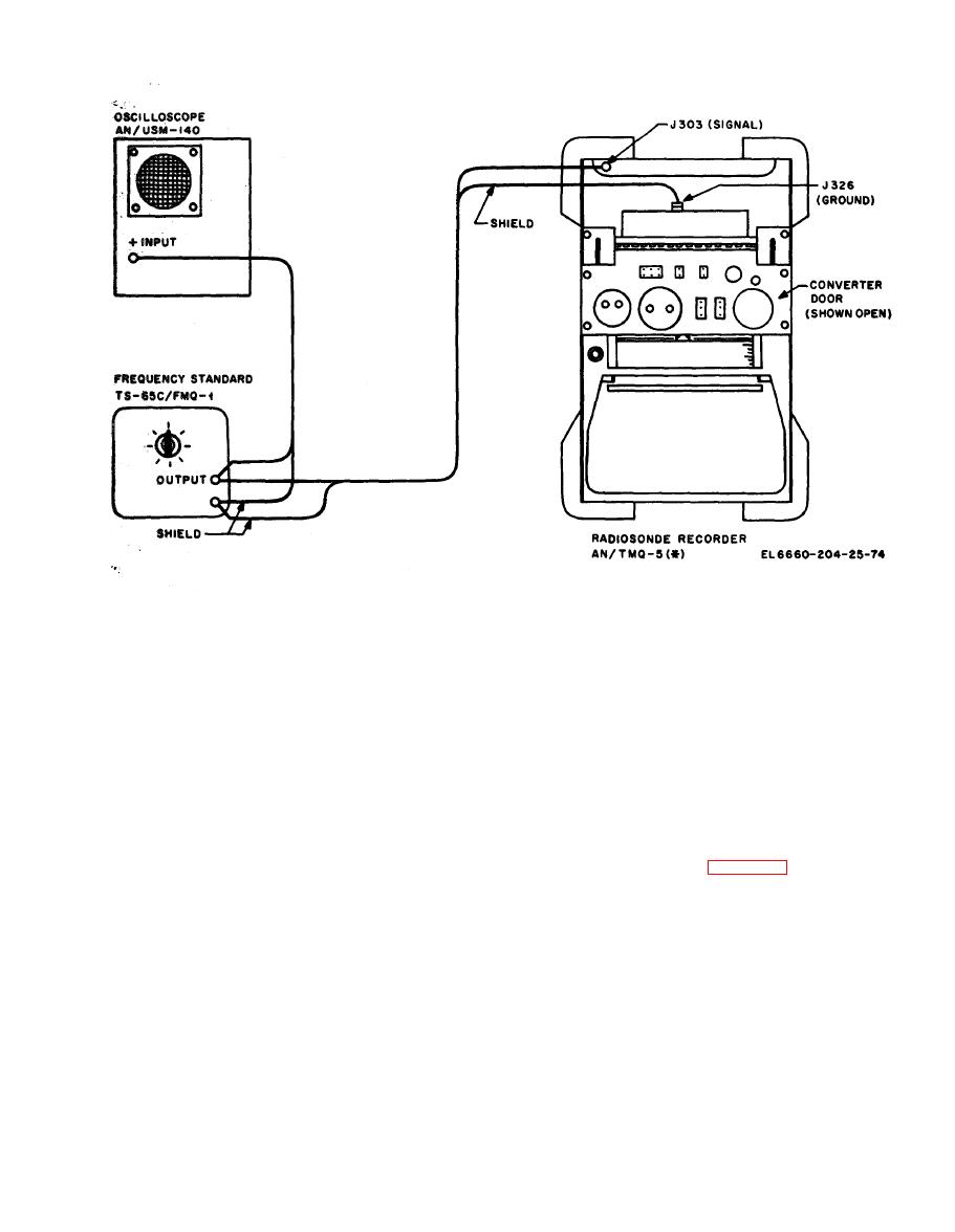
Figure 8-2. Standard test configuration. |
|
||
| ||||||||||
|
|  TM 11-6660-204-25
b. Operate the REC. ZERO adjustment to the
STANDBY position and measure the distance be-
extreme clockwise position which should position
tween the pen point and the chart, which should
the pen within chart division above zero. Then
be 1/16 inch.
operate the REC. ZERO adjustment to the ex-
b. Operate the control panel power switch to the
ON position and use the weighing scale to check
treme counterclockwise position, which should po-
pen pressure against the chart at the ball of the
sition the pen within chart division below zero.
pen, which should be 2 ounces.
c. Operate the REC. ZERO adjustment to posi-
8-10. Chart Feed
tion the pen at zero chart divisions.
a. The prime power source should be 60 Hz
when the chart feed test is checked. If the power
8-12. Reference Adjust Voltage
source is interrupted during the time check, re-
a. Connect the frequency standard to the radio-
peat the test.
sonde recorder as shown in figure 8-2.
b. Operate the chart rate speed set at inch
p e r minute. The chart should feed 15 1/64
b. The recorder must be capable of being ad-
inches (30 line spaces) in 30 minutes.
justed to 80 chart divisions when an input signal
c. Operate the chart rate speed at 1 inch per
f r e q u e n c y of 140 Hz to 190 Hz is applied.
minute (two and three-speed recorders only). The
(1) Adjust the frequency standard for a 190
c h a r t should feed 15 1/64 inches (30 line
Hz, 25-volt peak-to-peak signal.
spaces) in 15 minutes.
(2) Adjust the REF. ADJUST control until
d. Operate the chart rate speed set at 2 inches
the pen indicates 80 chart divisions.
p e r minute (three-speed recorders only). The
(3) Adjust the frequency standard for a 140
c h a r t should feed 30 1/32 inches (60 line
Hz, 25-volt peak-to-peak signal.
spaces) in 15 minutes.
(4) Adjust the REF. ADJUST control until
the pen indicates 80 chart divisions.
8-11. Zero Adjust
a. Operate the SIGNAL SELECTOR switch to
(5) Adjust the frequency standard for a 190
Hz, 25-volt peak-to-peak signal.
S.C. position.
Change
2
|
|
Privacy Statement - Press Release - Copyright Information. - Contact Us |
