 |
|||
|
|
|||
|
Page Title:
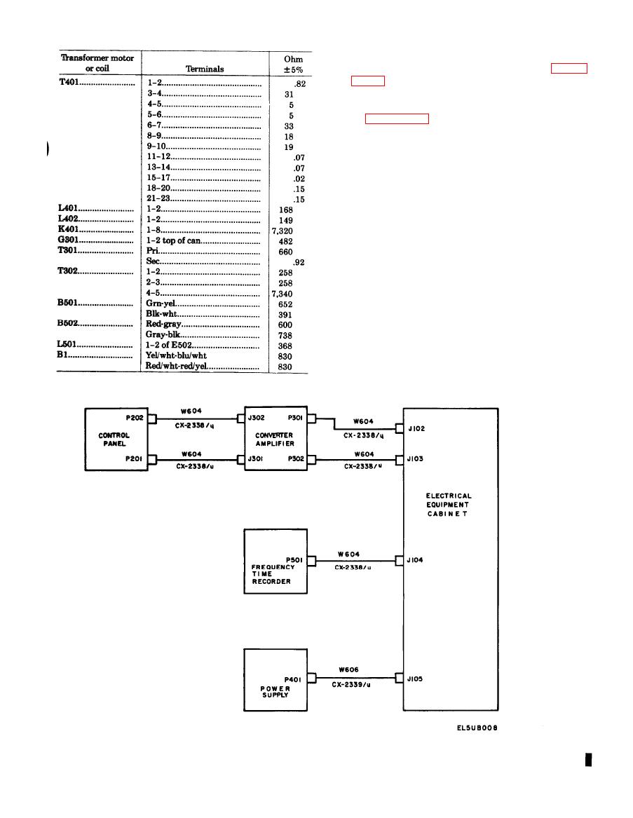
Figure 4-1. Radiosonde Recorder AN/TMQ-5(*), Cable Connections. |
|
||
| ||||||||||
|
|  TM 11-6660-204-25
oscilloscope between the test point specified on fig-
ure FO-15 and the chassis.
display the horizontal frequency shown on the wave-
form of figure FO-15. Set the vertical amplifier con-
trol so that the vertical component of the waveform
falls within the value specified.
c. In some cases it maybe necessary to unbalance
the detector to create a signal in the servo amplifier.
To unbalance the detector, place the SIGNAL SE-
LECTOR switch in the 60 CPS position and adjust
the REF. ADJUST control until the pen indicates 30
chart divisions. Operate the power switch (S201) to
the POWER OFF position. Disconnect the black and
white wires of balancing motor B501 from terminals
3 and 4 of terminal board E501. Operate the power
switch (S201) to the POWER ON position. Manually
rotate the slide and trolley wire arm until the pen
travels a distance corresponding to the percentage of
unbalance desired. (The number of chart divisions
that the pen travels from 30 chart divisions is equal
to the percentage of unbalance in the detector.)
Therefore, to obtain a 2-percent unbalance, rotate
the slide and trolley wire arm so that the pen will
Change 3 4 - 3
|
|
Privacy Statement - Press Release - Copyright Information. - Contact Us |
