 |
|||
|
|
|||
|
Page Title:
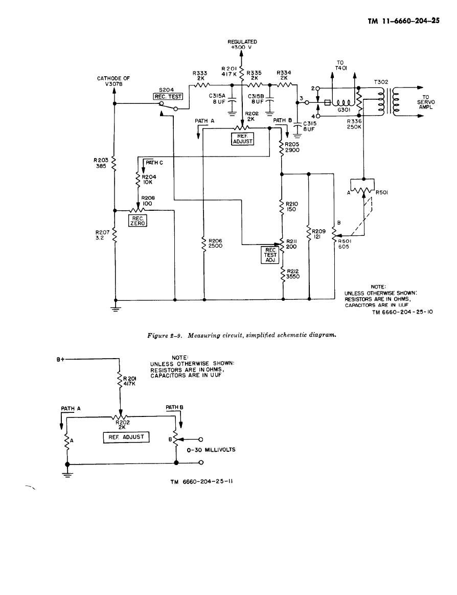
Figure 2-9. Measuring circuit, simplified schematic diagram |
|
||
| ||||||||||
|
|  The detector circuit converts the dc error voltage
into an ac voltage which is amplified until it
moves the balancing motor. The resulting motion
is imparted by mechanical coupling to the wiper
arm, which is another point of dc balance, At this
point, there is no longer any driving power and
the motor stops. This balance point is adjusted by
the calibration controls to give a chart trace that
may be translated into meteorological data.
a. The 030 millivolts of dc signal developed
across resistors R203 and R207 is applied through
the normally-closed contacts of REC. TEST
switch S204, on the control panel, through the
damping filter (which consists of R333, R334, and
R335 and three-section capacitor C315) to the vi-
brating reed of inverter G301. This voltage is al-
ternately applied to the two ends of the primary
schematic diagram.
"windings of transformer T302, 60 times a second
as the reed vibrates in synchronism with the ac
The balancing circuit sets in motion the action
applied to its operating coil. It is assumed that the
necessary to rebalance these potentials once a dif-
signal voltage at this instant is slightly greater
ference has occurred, and thus cancel the error.
|
|
Privacy Statement - Press Release - Copyright Information. - Contact Us |
