 |
|||
|
|
|||
|
|
|||
| ||||||||||
|
|  TM 11-6660-204-25
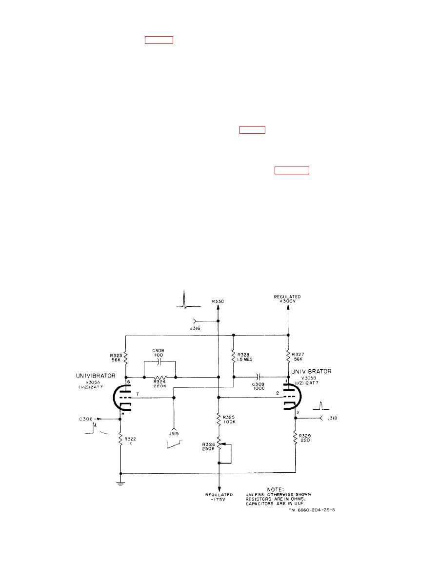
V306. Test jacks J315 and J316 (fig. 27) are
the reverse direction, and thus rapidly restores
provided to check the grid waveforms of tubes
the circuit to its original stable state with tube
V305A and V305B, respectively. The cathode
V305A conducting and tube V305B at cutoff.
waveform is shown at jack 318 of tube V305B.
d. The grid of tube V305B is directly connected
through resistor R330 to the grid of voltage
A positive pulse from the cathode of pulse
c.
switch tube V306; thus, the positive rectangular
selector tube V304A is impressed on the cathode
pulse created at this point (J316) is used to oper-
of tube V305A through capacitor C306, to reduce
ate V306.
the nearly zero bias to a high negative value
which reduces plate current and produces a posi-
2-11.
Voltage Switch and Output Gate
tive plate voltage swing because of the reduced
voltage drop across resistor R323. This plate volt-
age swing is coupled to the grid of tube V305B
a. Voltage switch V306 is a miniature, hi-rep,
through C308 producing a plate current flow
twin-triode tube. Both sections are connected in
which increases voltage drop across R327. Capaci-
parallel, but they are shown as a single tube in the
tor C308 permits the instantaneous signal swings
simplified diagram of figure 28 for ease of pres-
to bypass resistor R324 so that this steep rise is
entation. The output gate circuit utilizes both sec-
not attenuated at the grid of tube V305B. This
tions of miniature twin-triode tube V307 con-
negaive plate voltage swing is, in turn, coupled to
nected as twin diodes. The rectangular pulse out-
the grid of tube V305A by capacitor C309, caus-
put from the univibrator is utilized to develop an
ing regenerative action which rapidly increases
output pulse (one that is identical for each input
the negative swing on tube V305A so the tube is
pulse) by voltage switch tube V306 for applica-
immediately driven into cutoff. This new state of
tion to the output gate circuit. The output gate
conduction exists until capacitor C309 is dis-
functions to produce a 0- to approximately 30-mil-
charged sufficiently through resistor R328 to the
livolt output voltage that is proportional to the
point where the grid of tube V305A is brought
recurrence frequency of the input signal applied
above cutoff. Regenerative action then occurs in
to the recorder.
|
|
Privacy Statement - Press Release - Copyright Information. - Contact Us |
