 |
|||
|
|
|||
|
|
|||
| ||||||||||
|
|  TM
11-6660-204-25
charge drain; the plate voltage remains constant,
which eliminates the relatively high current re-
quired to charge the grid-plate capacity under or-
dinary amplification conditions. On the other
hand, the output impedance is low because the
plate, not having any external impedance to limit
its current, will supply any reasonable current de-
mands. (Output A = 1/Gm, nearly. )
Noise suppression diode V301B is one-half of a
miniature twin-triode tube which has had the
plate and grid pins connected together to form an
anode connection. The purpose of the diode is to
reduce the high noise level in the signal to prevent
false triggering of the univibrator giving false
recordings, The diode may be switched in or out
by means of the noise suppression switch (S301).
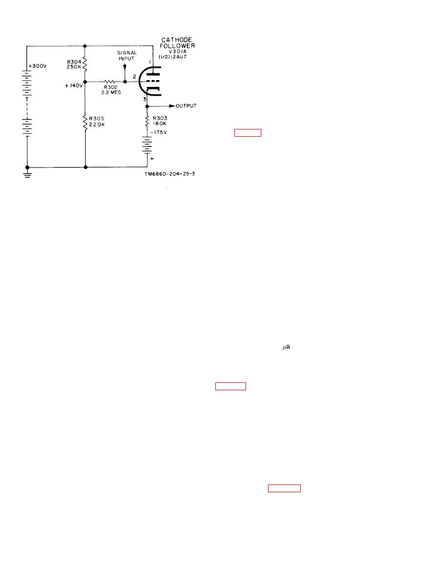
through R302. Cathode resistor R303 (180,000
When this switch is in the OUT position, the
ohms) is a return path to the negative 175-volt
anode and cathode are shorted together and the
supply, so across the plate-cathode resistance and
signal is bypassed around the diode; the tube is
R303 (in series) there isa tota! potential of 475
inoperative. The explanation that follows (switch
volts. Cathode current in resistor R303 keeps the
at the IN position) applies to actual noise sup-
cathode above the 140-volt potential of the grid, so
pression.
the tube actually has a negative bias. The advan-
tage of this circuitry permits the injection of
a. A small space current is present in the tube
large signal voltages without overloading, and
under no-signal conditions, because the anode is
presents a high impedance to the signal source but
connected to --300 volts through resistors R307,
a low impedance signal source to the load.
R306, and R304; and the cathode is connected to
(1) The higher signal voltage is permitted
--175 volts through resistor R303. Cathode resis-
tor R303 is shared with tube V301A and is the
because the cathode will follow closely any signal
voltage applied to the grid, avoiding any apprecia-
coupling between the two tubes. The portion of
ble change in grid-cathode potential. This action
the current in R303 that is delivered to tube
is probably best explained by an example: ('To
V301B is about 30
or 1/60 of the total current
simplify the figures, only approximate values are
in the resistor.
used).
b. The signal at jack J304 is practically identi-
(a) Assume the no-signal values of circuit
cal in amplitude and shape with that at jack J303
conditions to be--
Plate-cathode potential - - - - - - +151 volts
cathode of the diode. When the signal raises the
Grid-cathode potential - - - - - - 8 volts
cathode potential above that of the anode, the tube
IR drop across R303 -------- 324 volts
will not conduct. When the signal lowers the cath-
Plate (or cathode) current - - 1.8 milliampere
ode potential below that of the anode, the diode is
Transconductance - - - - - - - 2,500 umho.
able to conduct freely and can discharge any accu-
mulated charge in capacitor C302, the hot ter-
(b) This value of transconductance means
minal of which is connected to the anode through
a change in IP of 2.5 microampere (Pa) for each
switch S301.
millivolt change of grid-cathode potential. A posi-
tive grid signal swing of 50 volts would then
c. Under no-signal conditions the two cathodes
create a positive cathode signal swing of 49.9
of tube V301 will be about 150 volts potential
volts; the other tenth of a volt being a grid-cath-
above ground (para 23). Capacitor C302 will
ode change, permitting the increase in lP.
charge through resistors R307, R306, and R304;
the voltage across C302 will rise exponentially to-
(2) The grid input circuit of a cathode-fol-
ward that value determined by the setting of po-
lower stage is high impedance because the small
tentiometer R304. When this positive-going volt-
grid-ground capacity is the only one with any
2-4
|
|
Privacy Statement - Press Release - Copyright Information. - Contact Us |
