 |
|||
|
|
|||
|
Page Title:
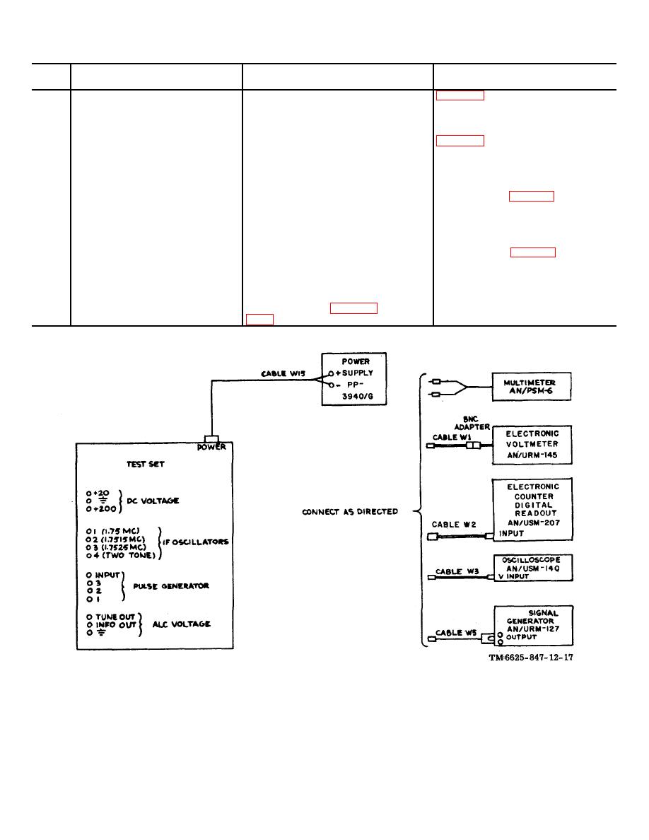
Figure 4-1. Test equipment for trouble localization in SM-442A/GRC. |
|
||
| ||||||||||
|
|  TM 11-6625-847-12
Stop
Control setting and
Performance standard and
No.
Operation of test equipment
operation of equipment
references
11
Connect AN/USM-140 to
Adjust PULSE GENERATOR
PULSE GENERATOR
(upper) WIDTH and AMPLI-
OUTPUTS 2 connector.
TUDE controls for a 150-usec,
1 volt negative pulse indication.
12
Connect AN/USM-140 to
Adjust PULSE GENERATOR
PULSE GENERATOR
(upper) WIDTH and AMPLI-
OUTPUTS 1 connector.
TUDE controls for 86
usec,
1 volt positive pulse indication.
13
Connect AN/PSM-6 dc
Rotate SERV SEL switch to
Output voltage should vary from
test leads between ALC
SSB/NSK. Adjust ALC VOLT
0 to 20 volts dc (para 4-15,
VOLTAGE TUNE OUT
AGE TUNE control from fully
item No. 11).
test connector and
counterclockwise to fully clock
ground.
wise.
14
Connect AN/PSM- d&
Rotate SERV SEL switch to
Output voltage should vary from
test leads between ALC
SSB/NSK. Rotate ALC VOLT
0 to 20 volts dc (para 4-15, item
VOLTAGE INFO OUT
AGE INFO control from fully
No. 12).
test connector and
counterclockwise to fully clock
ground.
wise.
15
Disconnect all test equip-
Reset all switches and controls
POWER indicator extinguishes.
ment.
to settings given in paragraph
Figure 4-1. Test equipment for trouble localization in SM-442A/GRC.
4-5
|
|
Privacy Statement - Press Release - Copyright Information. - Contact Us |
