 |
|||
|
|
|||
|
|
|||
| ||||||||||
|
|  TM 11-6625-847-12
CHAPTER 2
INSTALLATION
(7) Store the packaging material for future
2-1.
Unpacking
reshipment.
b. Unpack case 2 as follows:
a. Unpack case 1 as follows; use at least two men:
(1) Remove the second corrugated carton from
(1) Remove the klimp fasteners from the top
its plywood crate.
cover of the plywood crate.
(2) With a knife or any sharp instrument, slit the
(2) Remove the corrugated carton marked
tape which holds the top of the corrugated packing carton;
test set.
open the carton.
(3) With a knife or any sharp instrument, slit
(3) Remove the polyethylene shroud from case
the tape which holds the top of the corrugated packing
2.
carton; open the carton.
(4) Remove the four polystyrene corner pads
(4) Remove the polyethylene shroud from
from top of case 2.
case 1.
(5) With one man at the front and one at the
(5) Remove the four polystyrene corner pads
rear, lift case 2 from its crate.
from the top of case 1.
(6) Store the packaging material for future
(6) With one man at the front and one at the
reshipment.
rear, lift case 1 from its crate.
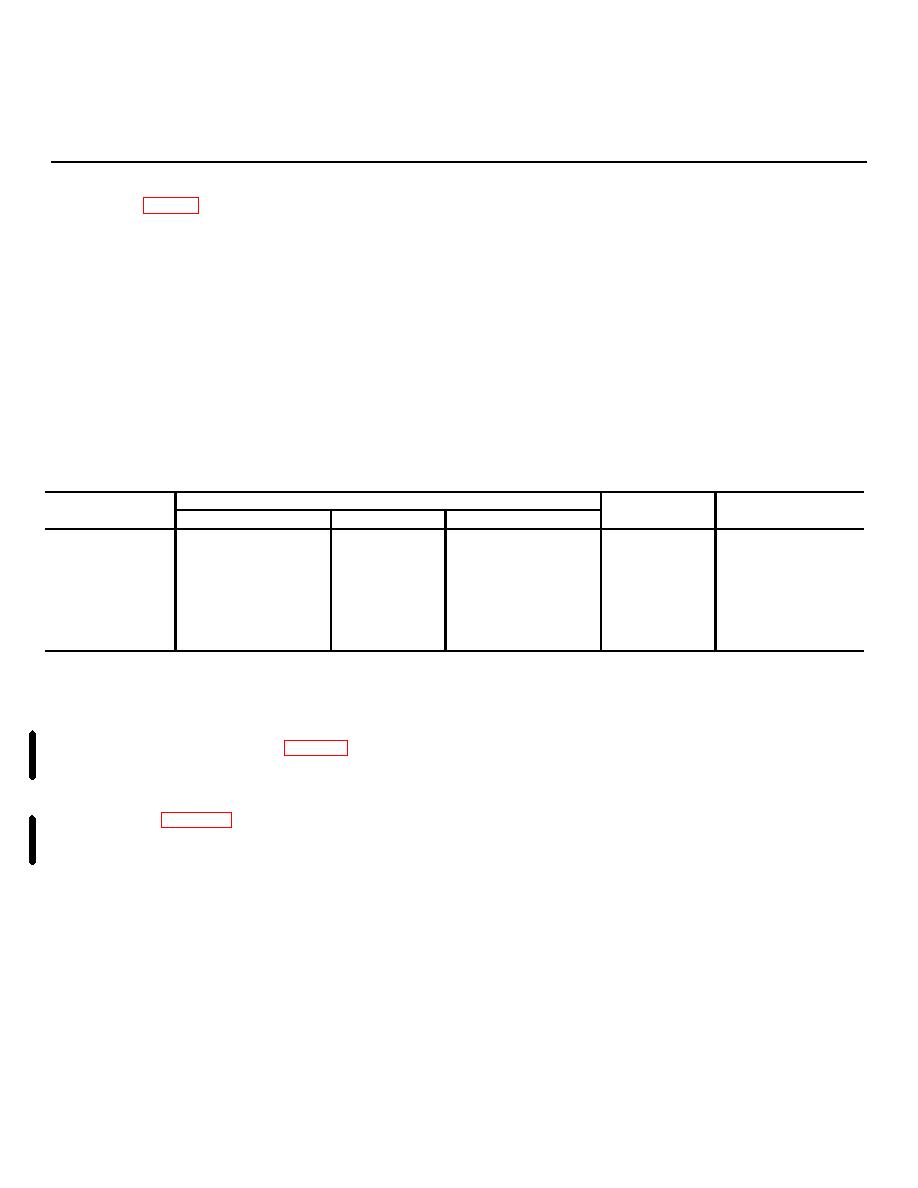
2-2.
SM-442A/GRC Shipping Container Chart
Dimensions (in.)
Case No.
Height
Width
Depth
Weight
Qty
Crated
2
30
23
26
32
1
1
30
23
26
73
1
1 and 2
51
33
31
130
1
Uncrated
2
22
20
20
30
1
1
22
20
20
70
1
When the SM442A/GRC is to be installed, the following
2-3.
Checking Unpacked Equipment
factors should be considered:
a. Inspect the equipment for damage incurred
a. Test Set (Case 2).
during shipment. If the equipment has been damaged,
(1) The test set must be located within 6 feet of a
report the damage on DD Form 6 (para 1-3b).
27-volt de, 100-ampere power source.
b. Check to see that the equipment is as listed on
(2) Case 2 has resilient bumpers for placement
the packing slip. If a packing slip is not available, check
on a workbench.
the equipment against the items comprising an operable
(3) A minimum 24by 24-inch space is required if
equipment list (para 1-6). Report all discrepancies in
case 2 is placed on a workbench.
accordance with instructions given in TM 38-750.
b. Storage Case (Case 1).
Storage of a minor assembly or part that does not affect
(1) Case 1 has no requirement for power.
the problem functioning of the equipment should not
(2) Case 1 has resilient bumpers for placement
prevent the use of the equipment.
on a workbench.
c. If the equipment has been used or
(3) A minimum 24by 24-inchl bench space is
reconditioned, check to see if it has been changed by a
required.
modification work order (MWO). If the equipment has
(4) If bench space is limited, the top of case 2 is
been modified, the MWO number will appear on the
dimpled so that case 1 may be stacked on top of case 2.
front panel near the nomenclature plate. Be sure that
any operational instruction changes resulting from the
2-5.
Initial Adjustment of Equipment
modification have been entered into the equipment
No initial adjustment of this equipment is required.
manual.
Note: Current MWO's applicable to the equipment
are listed in DA Pam 3104.
2-4.
Placement of Equipment
Change 2 2-1
|
|
Privacy Statement - Press Release - Copyright Information. - Contact Us |
