 |
|||
|
|
|||
|
|
|||
| ||||||||||
|
|  p r o d u c e a zero db pointer de flee-
attenuator. Use the applicable tuning unit
tion on the panel meter.
s i g n a l generator (para 81) for the tuning
b. Set the IMPULSE GENERATOR DB
unit under test.
b. Operate the test set front-panel con-
A B O V E lV/MC switch to the ON posi-
t r o l s as follows:
tion, and set the impulse generator coarse
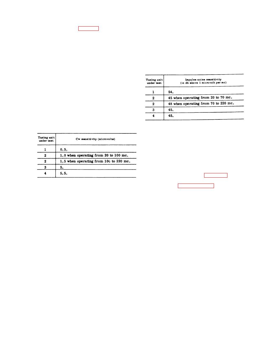
(1) Set the SIGNAL ATTENUATOR DB
and fine output level controls to produce a
2 0 - d b indication on the panel meter. The
control to the 0 CW ONLY position.
sum of the coarse and fine output control
(2) Set the function switch to the CW
s e t t i n g s must not exceed the value listed
AVERAGE position.
in the following chart:
( 3 ) Set the calibration switch to the
SERIES CAL & OPERATE position.
c. Adjust the tuning unit signal generator
o u t p u t level control and the test tuning
unit GAIN control to produce a panel meter
d e f l e c t i o n of 10 microvolt.
d. Reduce the tuning unit signal gener-
a t o r output level to zero, and record the
r e s i d u a l noise level indicated on the test
s e t panel meter. This residual level must
n o t exceed the value listed in the chart
C.
Repeat the procedures
given in a
that follows:
and b above at the high and
low ends of
e a c h frequency band, and at
five equally
s p a c e d frequencies over each
band.
107. Image Rejection
a. With a tuning unit plugged into the
m a i n unit, connect the applicable tuning
u n i t signal generator for the tuning unit
under test as directed in para 105a.
b. Set the test set front-panel controls
as directed in paragraph 105b.
e. R e p e a t t h e p r o c e d u r e s g i v e n i n a
c. Tune the tuning unit signal generator
through d above at the high and low ends
to the lowest frequency of the tuning unit
of each frequency band, and at five equally
under test and adjust the tuning unit sig-
spaced frequencies over each band.
nal generator output level control and the
tuning unit GAIN control to produce a full-
106. Impulse Noise Sensitivity
scale indication on the test set panel meter.
Use a 1-microvolt test signal when
lowing test.
checking tuning unit 1; use a 10-microvolt
a. Set the test front-panel controls as
test signal when checking tuning unit 2, 3,
follows:
or 4. Record in db the tuning unit signal
(1) T h e SIGNAL ATTENUATOR DB
generator output level control setting
switch to the 0 SUBST ONLY posi-
r e q u i r e d to produce the full-scale panel
tion.
m e t e r indication.
(2) The function switch to the PULSE
d. Retune the tuning unit signal gener-
PEAK position.
ator to the nearest image frequency, which
(3) The calibration s w i t c h to the
i s twice the if. of the tuning unit under
SHUNT CAL position.
test, plus the fundamental tuned frequency.
(4) T h e IMPULSE GENERATOR DB
T y p i c a l image frequencies for the low-
ABOVE lV/MC switch to the OFF
e s t frequency of each band of the four
position.
t u n i n g units are listed in the following
(5) T h e tuning unit GAIN control to
chart:
223
|
|
Privacy Statement - Press Release - Copyright Information. - Contact Us |
