 |
|||
|
|
|||
|
Page Title:
Alignment of Rf Tuner Section, Tuning Unit 3 |
|
||
| ||||||||||
|
| 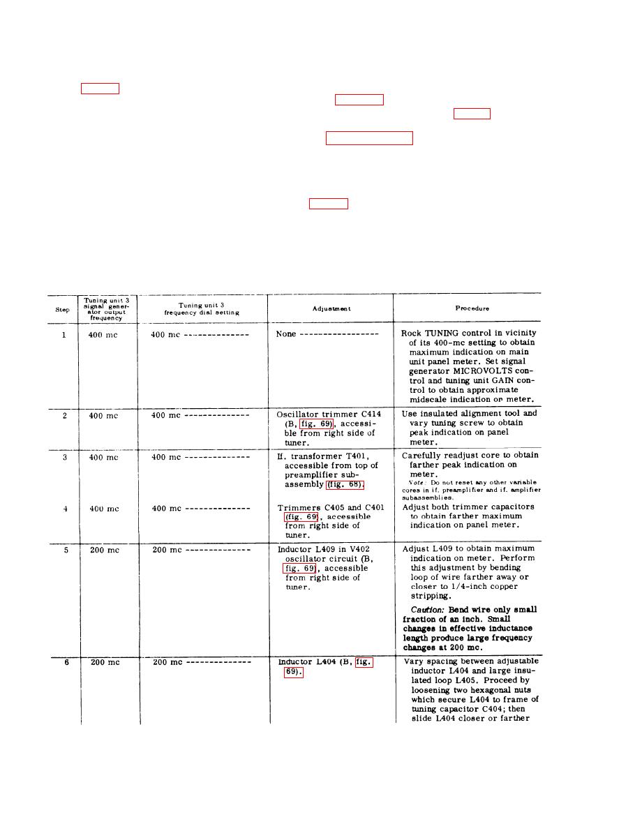 94. Alignment of Rf Tuner Section,
a. Align the rf tuner while tuning unit 3
is operating outside of the main unit and
Tuning Unit 3
the main unit removed from its instrument
case (para 40b, item 12, TM 11-6625-351-
Warning: Short lengths of uninsulated
12). Use the test harness (fig. 46). Set the
metal strapping are used as rf inductors in
front-panel controls to the positions listed
the tuning unit 3 rf tuner because of the
i n paragraph 88c, e x c e p t for the FRE-
u l t r a - h i g h frequencies employed. Never
QUENCY-RANGE MC switch. Tuning unit
touch the inductors with the bare fingers
3 has no bandswitch.
while the operating power is applied. Al-
b. Remove the two access covers from
ways use a well-insulated pair of pliers
t h e left and right sides of the rf tuner
or an insulated screwdriver in making ad-
justments within the rf tuner. Remove the
c. Inject the output of the tuning unit 3
operating power before making an adjust-
s i g n a l generator to the main unit front-
ment. Change the position of an inductor,
panel SIGNAL INPUT jack; use Cord
a n d then reapply operating power after
C G - 5 5 B / U supplied with the generator.
the adjustment has been made, in order to
Proceed as directed in the following
avoid shock hazard to maintenance per-
chart:
sonnel.
204
|
|
Privacy Statement - Press Release - Copyright Information. - Contact Us |
