 |
|||
|
|
|||
|
Page Title:
Detector and Electrometer Assembly A201 |
|
||
| ||||||||||
|
|  Cathode bias is employed; the bias
The fourth if. amplifier ( V 2 1 0 ) operates
r e s i s t o r is bypassed by a capac-
i n a n i d e n t i c a l m a n n e r w i t h V209. The
itor. A tuned coil is in series with
o u t p u t signal from the tuned impedance
the cathode bias network to chassis
n e t w o r k 2202 is coupled to if. cathode
ground. This coil is adjusted dur-
follower V211.
i n g if. amplifier alignment to de-
velop maximum signal output.
A cathode follower is used as the final
(3)
The c o m m o n junction of the
s t a g e in the if. amplifier subassembly.
s c r e e n grid, the suppressor grid,
T h i s stage is identical in circuit compo-
and the plate is bypassed to ground
nents with the if. cathode follower in tuning
t h r o u g h a capacitor. Plate volt-
units 2, 3, and 4. Therefore, the following
a g e is applied from the filtered
c i r c u i t description is applicable to all if.
1 5 0 - v o l t bus through a dropping
c a t h o d e followers, with differences indi-
resistor.
cated in the chart that follows the circuit
analysis.
(4)
The heater circuit is decoupled
from the 6.3-volt ac power
(1) The function of the if. cathode fol-
s o u r c e by a filter capacitor and
lower is to supply driving power to
rf choke.
t h e detectors in the detector and
e l e c t r o m e t e r circuit from a low-
T h e rf voltage developed across
(5)
i m p e d a n c e source.
t h e cathode tuned coil is applied
t o a connector plug on the rear
(2) A pentode-type 6BJ6 tube is used
p a r t i t i o n of the if. amplifier sub-
a s the if. cathode follower; since
a s s e m b l y. This connector plug
the screen grid, the suppressor
mates direct with input jack J1 on
g r i d , and the plate are externally
t h e detector and electrometer as-
connected together, the tube func-
sembly.
t i o n s like a triode. The if. signal
from the final if. amplifier is cou-
(6)
T h e following chart summarizes
pled to the grid of the triode. The
the differences between the if.
r e s i s t o r housed within the imped-
c a t h o d e followers in tuning units
2, 3, and 4.
ance network of the final if. ampli-
f i e r functions as the grid return.
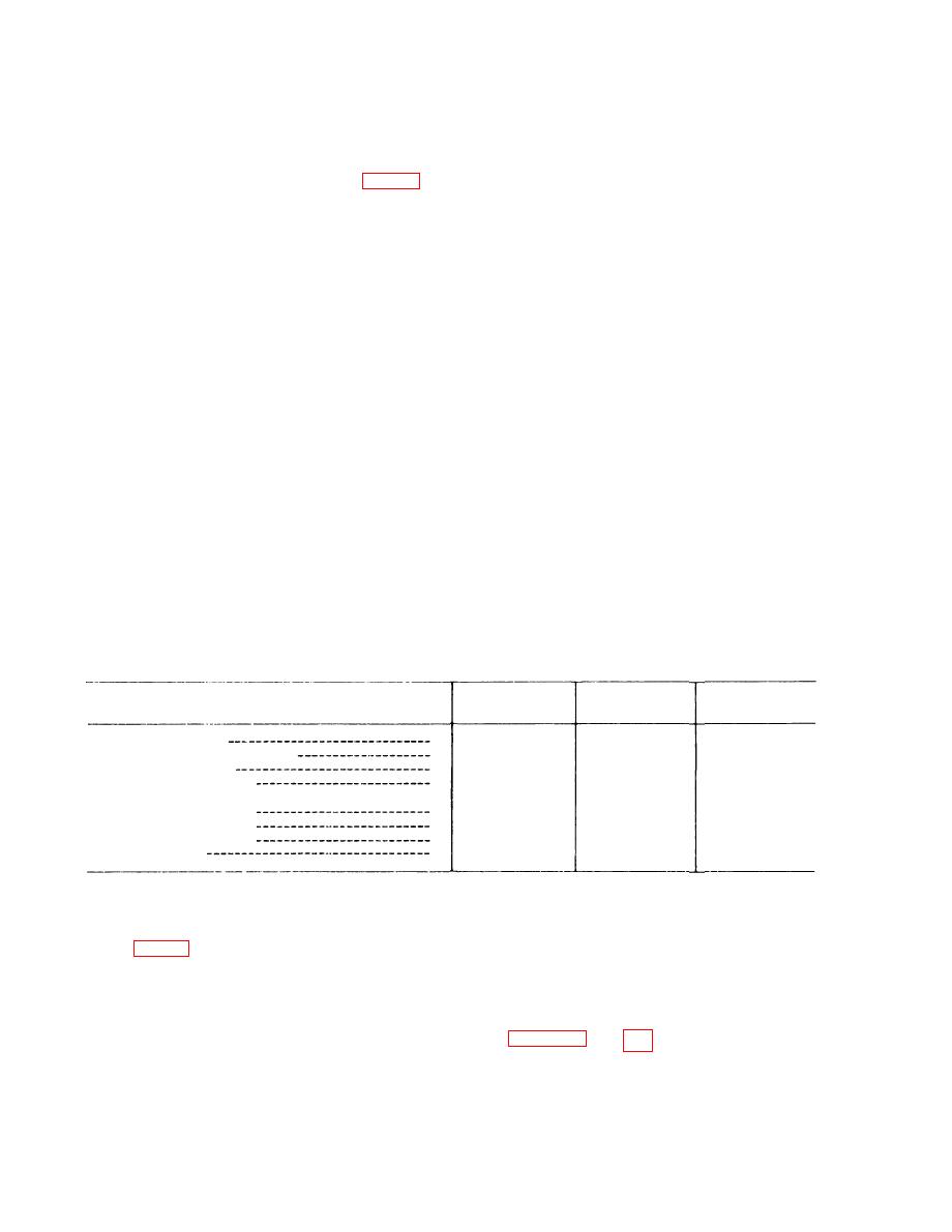
Tuning unit
Tuning unit
Tuning unit
Component
2
3
4
If. cathode follower
V211
V512
V410
Grid input parasitic suppressor
None
R462
R584
Cathode bias resistor
R271
R463
R585
Cathode bypass capacitor
C293
C488
C593
Plate voltage-dropping resistor and bypass capacitor
R272 and C294
R464 and C491
R586 and C594
Plate decoupling network
R269 and C295
R459 and C492
R581 and C603
Heater decoupling circuit
C306 and L235
C489 and L432
C609 and L542
Tuned cathode inductance
L431
L229
L535
P212
P413
Output connector
P514
separate audio and dc metering signal
41. Detector and Electrometer
channels, and applies output signals to the
Assembly A201
appropriate circuits in the main unit.
T h e s e sealed assemblies are interchange-
able with each other and perform the func-
All tuning units use an identical sealed
t i o n s described in detail for detector and
d e t e c t o r and electrometer assembly. Each
e l e c t r o m e t e r assembly A1 within tuning
assembly receives driving power from the
i f . amplifier, s e p a r a t e s the signal into
58
|
|
Privacy Statement - Press Release - Copyright Information. - Contact Us |
