 |
|||
|
|
|||
|
Page Title:
Figure 17. Tuning unit 1 if. input selector and if. step attenuator, schematic diagram. |
|
||
| ||||||||||
|
| 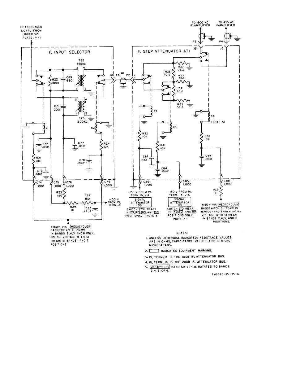 Figure 17. Tuning unit 1 if. input selector and if. step attenuator, schematic diagram.
by the same voltage as K1, and is energized
a t the same time. Feedthrough capacitor
c o n t r o l s the movable contact that selects
C79 is an rf bypass. Resistor R24 serves
the output of either T22 or T23 to feed if.
a s the voltage-dropping resistor in the
step attenuator AT1. This relay is activated
40
|
|
Privacy Statement - Press Release - Copyright Information. - Contact Us |
