 |
|||
|
|
|||
|
Page Title:
Chapter 2. BASIC PULSE-CODE MODULATION PRINCIPLE |
|
||
| ||||||||||
|
|  TM 11-5895-45-14
CHAPTER 2
BASIC PULSE-CODE MODULATION PRINCIPLE
Section I. INTRODUCTION
channel is assigned a time interval in sequence with all
2-1. General.
other channels being multiplexed. These intervals are
a. The TD-204/U or TD-754/G, TD-206/G, and TD-
short and repeated at a high frequency. The samples
660/G or TD-660A/G are pulse-code modulation
taken from each channel are then converted to a form
components used as part of multichannel communication
suitable for transmission in the selected medium. At the
systems.
These systems use radio or cable, or
receiving terminal, the samples are demodulated and
combinations of both as a transmission medium. The
separated into their proper channels by a timing signal
pcm components provide 6 or 12 audio channels in a
from the transmitting terminal.
single transmission channel.
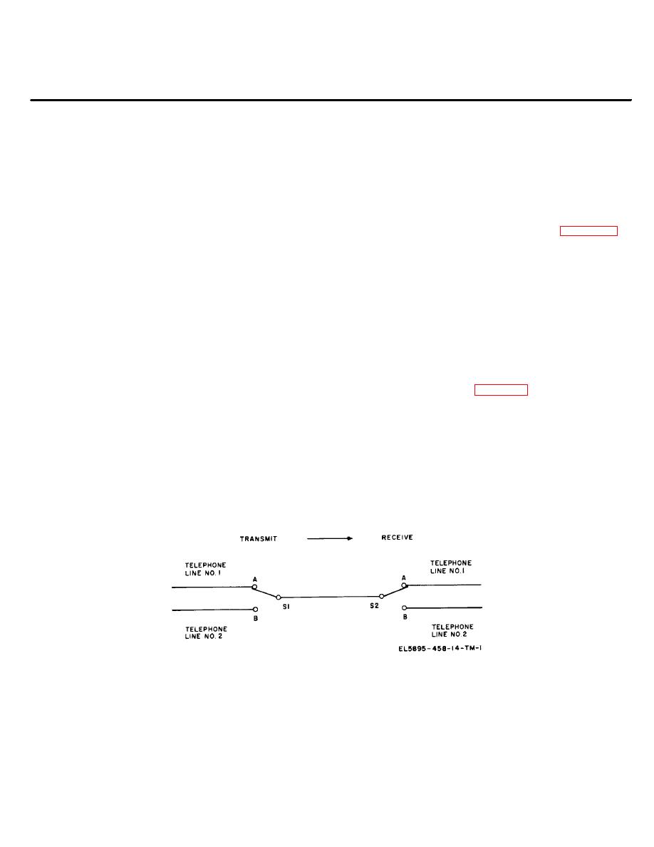
(2) The simplified telephone circuit in figure 2-1
b. In a 12-channel system, separate telephone
illustrates the time division principle. Switches S1 and
signals are converted to pulse-code-modulation (tdm-
S2 are synchronized such that both are in position A at
pcm) pulse trains, for radio transmission. The two pulse
the same time, and in position B at the same time. A
trains are interleaved and transmitted over a single radio
telephone call made on line A is completed only when
channel, and reconverted to telephone signals at a
the switches are in position A. The telephone calls made
distant terminal.
on line B are completed only when the switches are in
c. The 12-channel system also provides for the
position B. When both lines are in use, the switches
capability for pulse trains to be reshaped and retimed at
alternate between position A and position B. If the
a repeater point in the system, and reconverted to
switching rate is low, both conversations will be garbled
telephone signals at another terminal. The repeater can
and unintelligible. If the rate is increased, the signals will
therefore communicate in both directions, and with both
be more intelligible. When the switching rate is higher
terminals, and can be either a radio or cable repeater, or
than voice frequencies, the switching is not detectable.
a combination for radio-to-cable conversion.
(3) The circuit shown in figure 2-2 is a simplified 12-
2-2. Principles of Multiplexing
channel tdm system. The two switches are rotated in
a. General. Multiplexing is a technique used to
synchronism and each channel is sampled once during
transmit simultaneously several channels of voice or
each revolution. Very little distortion occurs and the 12
data over a radio or cable link. Frequency division-
conversations are intelligible when the rotation speed is
multiplexer (fdm) equipment utilizes a subcarrier
rapid enough. Electronic switching is used in the pcm
frequency for each voice or data channel. In time-
components described in this manual and 12 samples
division-multiplexer equipment, each voice or data
are
taken
in
each
time
frame.
channel shares the transmission time and is
intermittently transmitted.
b. Time Division Multiplexing.
(1) In time division multiplexing, each voice
Figure 2-1. Simplified telephone system showing simple tam.
2-1
|
|
Privacy Statement - Press Release - Copyright Information. - Contact Us |
