 |
|||
|
|
|||
|
Page Title:
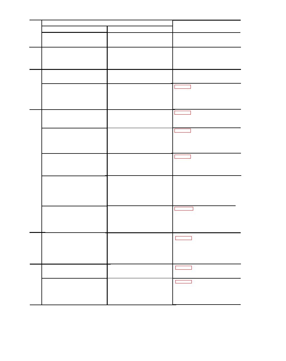
Periodic Maintenance Service and Inspection Chart (cont) |
|
||
| ||||||||||
|
|  Procedure
Item
References
No.
Item
Normal condition or result
up for 5 minutes and set the
MODE 1 code control to an oper-
ating frequency.
None observable.
TM 11-6625-509-12.
STARTING; TRONSPONDER TEST
12
SET: Set the CODE selector
switches on the transponder test
set to the same code setup being
used on the transponder set.
The CODE flag on the transponder
TM 11-6625-509-12.
OPERATION; TRANSPONDER
13
TEST SET: Set the transponder
test set appears each time the
mode flag changes.
test set automatically.
The CODE and mode 1 flags should
NORMAL OPERATION; MODE 1:
14
appear on the transponder test
Set the transponder set control
set.
unit function control to NORMAL
Set the master control to NORM.
Set the AUDIO, I/P, MODE 2,
and MODE 3 switches to OFF.
The CODE and modes 1 and 2 flags
NORMAL OPERATIONS; COM-
15
should appear on the transponder
BINED MODES 1 AND 2: Set the
MODE 2 switch on the trans-
test set.
ponder control unit to ON.
The CODE and modes 1 and 3 flags
NORMAL OPERATIONS; COM-
16
should appear on the transponder
BINED MODES 1 AND 3: Set the
MODE 2 switch on the trans-
test set.
ponder set control unit to OFF
Note: I/P and EMER flag may appear
during this test.
and set the MODE 3 switch to
ON.
NORMAL OPERATION; COM-
The CODE and modes 1, 2, and 3
17
flags should appear on the trans-
BINED MODES 1, 2, AND 3:
ponder test set.
Set the MODE 2 switch on the
transponder set control unit to
Note: l/P and EMER flag may appear
during this test.
ON.
TM 11-6625-509-12.
NORMAL OPERATION; COM-
The CODE flag appears when the
18
PLEMENTS OF MODES 1 AND
mode 1 and mode 3 flag appear.
3: Switch the transponder set
control unit MODE 1 and MODE
2 code controls to the comple-
ments of the modes 1 and 3 codes
on the transponder test set.
MOD OPERATION: Repeat items
Same as items 14 through 18.
19
14 through 18, except set trans-
ponder set control unit function
control to MOD and set MODE
1 and MODE 3 code controls to
assigned two digit code numbers.
CIVIL OPERATION: Repeat items
20
Same as items 14 through 18.
14 through 18, except set
transponder set control unit
function control to CIVIL and
set MODE 1 and MODE 3 code
controls to assigned two digit
code numbers.
21
The I/P flag appears on the trans-
I/P OPERATION: Repeat item 14,
except place I/P switch to I/P
ponder test set when the mode
position momentarily.
1 flag appears.
EMERGENCY OPERATION: Push
The I/P and EMER flags appear
22
transponder set control unit
on the transponder test set when
emergency barrier button in and
mode 1 flag is in view.
simultaneously turn the master
control switch to EMER. Release
emergency barrier button.
19
|
|
Privacy Statement - Press Release - Copyright Information. - Contact Us |
