 |
|||
|
|
|||
|
Page Title:
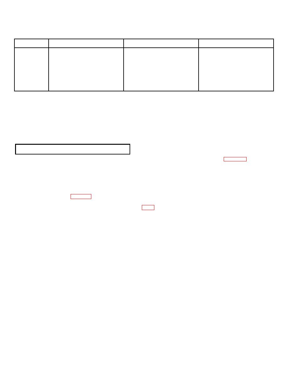
Table 3-1. TRANSMITTER/RECEIVER CONNECTIONS |
|
||
| ||||||||||
|
|  TM 11-5895-1141-34
Table 3-1. TRANSMITTER/RECEIVER CONNECTIONS
Channel
Transmit Audio
Receive Audio
Keying
1
J201-1 & 17
J201-3 & 19
J201-4 & 18
2
J201-5 & 21
J201-7 & 23
J201-8 & 22
3
J201-9 & 25
J201-11 & 27
J201-12 & 26
4
J201-13 & 29
J201-15 & 31
J201-16 & 30
5
J202-1 & 17
J202-3 & 19
J202-4 & 18
6
J202-5 & 21
J202-7 & 23
J202-8 & 22
7
J202-9 & 25
J202-11 & 27
J202-12 & 26
8
J202-13 & 29
J202-15 & 31
J202-16 & 30
NOTE
In the four wire mode operation, the keying wires are omitted.
with each audio unit; P201, P202 are furnished with each selector unit. The units must have a common chassis ground
which is achieved by wiring each chassis together with 20 gauge bus wire by attaching the wire to the screw-on terminals
located in the rear. Pin C on J105 connects the power supply ground to the audio unit chassis ground. 16 gauge wire
should be used to connect the +24 v line from the power supply to J105.
3-6. TEST AND ADJUSTMENT OF EQUIPMENT
With the installation completed, the system test procedures should be performed, as described in chapter 4, section II.
Following the system test, the following final adjustments should be made:
a. Transmitting Circuits. The equipment is placed in the transmitting mode of operation, with a 1000 Hz signal
applied to the microphone input, and simulated load connected to the output at which the resulting signal is measured.
b. Set up the equipment to provide a 0 dBm transmitting output level with a microphone input level of -11 dBm,
following the procedure in table 4-7, steps 1, 2, 3.
c. Reset the transmit level adjust control, R1230 (fig. FO-7), in the microphone amplifier/lamp brightness module
assembly to provide the desired transmitting output level. This adjustment may be rechecked, and a finer adjustment
made when the actual audio line to the transmitter is connected.
3-4
|
|
Privacy Statement - Press Release - Copyright Information. - Contact Us |
