 |
|||
|
|
|||
|
|
|||
| ||||||||||
|
|  T.O. 12P4-2APX-142
NAVAIR 16-35C6280-l
TM 11-5841-268-25
724. MODE 4 REPLY INDICATOR LIGHT. To check
indicated cannot be obtained, the trouble is isolated to the
MODE 4 REPLY indicator light DS201, turn lens cap fully
specific circuit being tested.
counterclockwise to open dimmer. Set AUDIO-OUT-LIGHT
720. PANEL LIGHT CHECK.
switch to AUDIO or LIGHT (lamp will not operate if switch
CAUTION
is in OUT position). On J201, connect positive lead of 28-
volt DC power supply to pin 51 and connect negative lead
Do not apply a voltage greater than 5 volts to
to pin 31. Press lens cap in (press-to-test) and check that
the panel light circuit of the C-6717/APX or the
lamp lights. Release cap, and connect positive lead of power
C-7483/APX. If the panel lamps are burned out,
the entire plastic panel must be replaced.
supply to pin 42 of J201; lamp should light. Disconnect
power supply.
721. For all transponder set controls, voltage for the panel
light circuit is applied through pins 12 and 53 of J201; how-
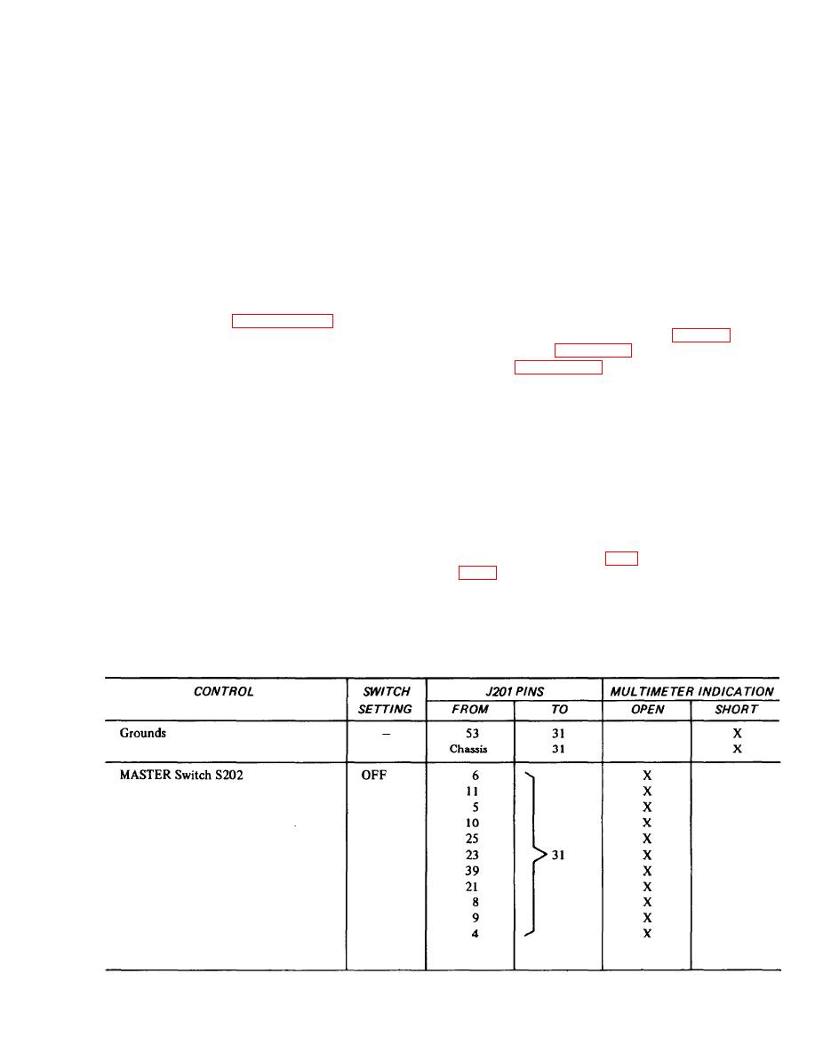
725. CONTROL SWITCH CHECK.
ever, the voltage required varies with the transponder set
726. The control switches and their circuits are tested by
making the continuity checks listed in Table 71. Use the
C-6280(P)/APX and the C-6280A(P)/APX may be equipped
multimeter listed in paragraph 32 and the test wiring de-
with either 6-volt or 28-volt panel lamps. Since these lamps
scribed in paragraph 35. Set the multimeter to indicate
are directly interchangeable, determine the voltage rating
continuity and connect the leads to the specified pins of
of the lamps installed in the unit being tested. For all the
J201. When the multimeter indications listed are not ob-
transponder set controls, connect the positive lead of the
tained, the malfunction is immediately isolated to the cir-
appropriate voltage supply to pin 12 of J201 and connect
cuit under test. It is not necessary to follow the order of
the negative lead to pin 53. Check that all panel lamps light.
checks as listed; any switch function may be checked indi-
7-22. INDICATOR LIGHT CHECK.
vidually, as required. When making the continuity checks,
723. TEST INDICATOR LIGHT. To check TEST indica-
unless otherwise instructed, all toggle switches are set to the
tor light DS202, turn the lens cap fully counterclockwise to
OFF or OUT position, the MASTER switch is set to any
open dimmer. On J201, connect positive lead of 28-volt DC
position except EMER, and the CODE switch is set to any
power supply to pin 51 and connect negative lead to pin 31.
position. To aid in understanding the significance of the
Press lens cap in (press-to-test) and check that lamp lights.
various switch settings and the resulting indications, refer
Release cap, and connect positive lead of power supply to
to the schematic diagram (FO-1) and the wiring diagram
pin 46 of J201; lamp should light. Disconnect power supply.
TABLE 71. CONTROL SWITCH CONTINUITY CHECKS
7-3
|
|
Privacy Statement - Press Release - Copyright Information. - Contact Us |
