 |
|||
|
|
|||
|
Page Title:
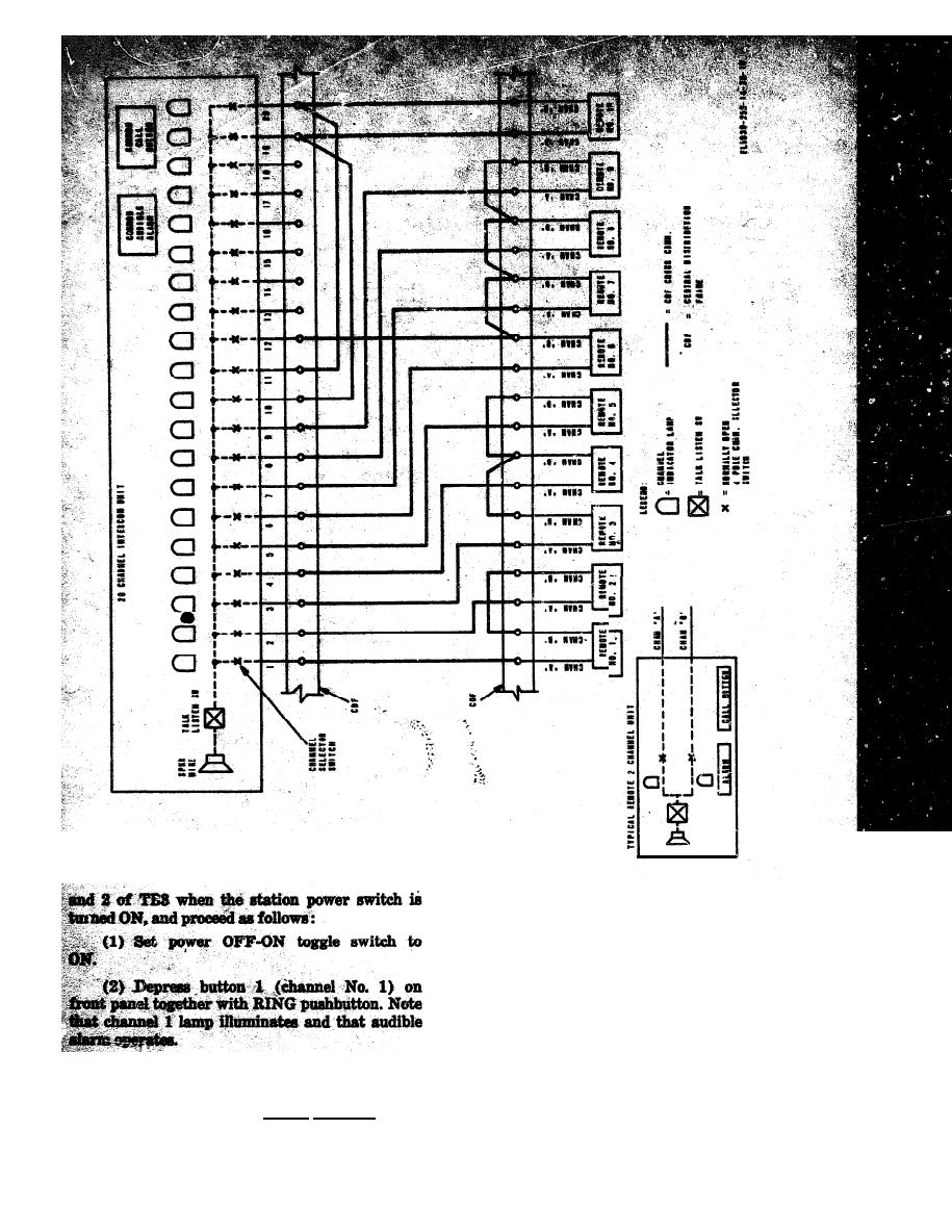
Figure 2-4. Typical intercom cross-connect diagram. |
|
||
| ||||||||||
|
|  TM 11-5830-255-14
(8) Depress REL pushbutton and note that
number 1 channel light extinguishes and that the
pushbutton returns to its normal position.
(4) Perform steps 4 and 6 for all 20 push-
buttons, one at a time, and note that lamps and
audible alarm operate properly.
c. Arrange for two or more persons to parti-
cipate in tests between the central intercom unit
|
|
Privacy Statement - Press Release - Copyright Information. - Contact Us |
