 |
|||
|
|
|||
|
Page Title:
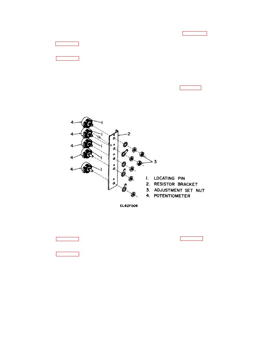
Removal and Replacement of Resistor Bracket Potentiometers |
|
||
| ||||||||||
|
|  TM 11-5825-271-34
b. Replacement. Proceed as follows
3-8. Removal and Replacement of Resistor Bracket
(1) Refer to figure 3-3. Install replacement
Potentiometers
potentiometer (4) on the resistor bracket (2). Ensure that
a. Removal. Proceed as follows
the locating pin (1) is properly seated in the hole in
(1) Refer to figure 3-1 Disengage two captive
resistor bracket, and that the terminal designations
screws (12) on the control panel assembly (13) and
(stamped on the resistor bracket) correspond with the
swing the control panel assembly out.
potentiometer terminals.
(2) Refer to figure 3-3. Slide rubber sleevings
(2) Secure potentiometer (4) to the resistor
off terminals on potentiometer (4) to be removed.
bracket (2) using the attaching hardware. Replace
(3) Tag and unsolder all wires connected to the
adjustment set nut (3) if either R5 or R6 is installed.
potentiometer (4).
(3) Solder all tagged wires to potentiometer (4)
(4) Remove all attaching hardware securing the
and slide rubber sleevings over connections.
potentiometer (4).
(4) Refer to figure 3-1. Swing the control panel
NOTE
assembly (13) in and tighten two captive screws (12).
When removing potentiometers R5 and R6,
it is necessary to remove the adjustment set
nut (3) before removing the attaching
hardware.
Figure 3-3. Removal and Replacement of Resistor Bracket Potentiometers.
(5) Raise the control panel (17), the relay
3-9. Removal and Replacement of Relay Bracket
bracket assembly (15) is now free to be removed
Assembly
b. Replacement. Proceed as follows.
a. Removal. Proceed as follows
(1) Refer to figure 3-2. With the control panel
(1) Refer to figure 3-1. Disengage two captive
(17) partially closed, position the relay bracket assembly
screws (12) on the control panel assembly (13) and
(15) so that the shafts of the potentiometers are directed
swing the control panel assembly out.
towards the bushings (14) in the control panel.
(2) Refer to figure 3-2. Slide rubber sleevings
(2) Aline the mounting holes in the relay bracket
off the potentiometer terminals on the relay bracket
assembly (15) with the two holes in the control panel
assembly (15).
(17).
(3) Tag and unsolder all wires connected to the
(3) Install and tighten two screws (1) and flat
components on the relay bracket assembly (15) from
washers (2) to secure the relay bracket assembly (15) to
sources outside the assembly.
Leave all rubber
control panel (17).
sleevings on wires for reassembly
(4) Swing the control panel (17) out, and solder
(4) Swing the control panel (17) in and remove
all tagged wires to the relay bracket assembly (15) Slide
two screws (1) and flat washers (2) securing the relay
rubber sleevings over the connections.
bracket assembly (15) to the control panel.
rubber sleevings over the connections.
3-5
|
|
Privacy Statement - Press Release - Copyright Information. - Contact Us |
