 |
|||
|
|
|||
|
Page Title:
Chapter 2. OPERATING INSTRUCTIONS |
|
||
| ||||||||||
|
|  TM 11-5825-270-10
CHAPTER 2
OPERATING INSTRUCTIONS
Section I. CONTROLS AND INDICATORS
2-1. Damage From Improper Control ettings
S
The monitor receiver is designed to preclude the possibility of equipment damage or injury to operating
personnel from improper control settings.
2-2. Controls and Indicators
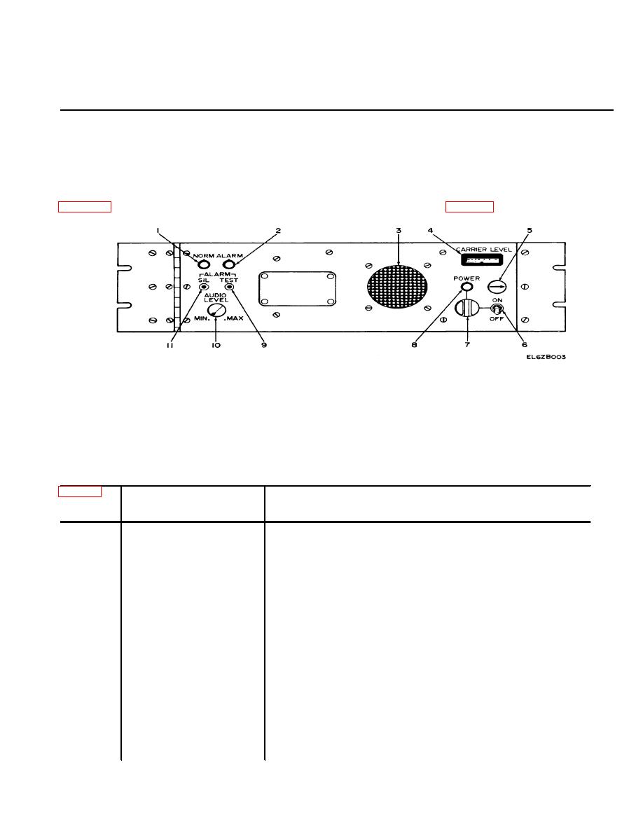
Figure 2-1 shows the front panel controls and indicators for the monitor receiver. Table 2-1 details the function
and use of each control and indicator.
Figure 2-1. Operator Controls and Indicators.
Table 2.1 Operator Controls and Indicators
Index
Control/Indicator
Function
No.
1
NORM Light ..............
Lights during normal operation; remains off during alarm
condition.
2
ALARM Light ............
Lights when an alarm condition exists; remains off during normal
operation.
3
Loudspeaker .............
Presents the modulation tones (keying) during normal operation.
Presents a loud 3-kHz tone during alarm condition.
4
CARRIER LEVEL Meter
Indicates the relative strength of the signal picked up by the whip
antenna. At the time of installation, the receiver is adjusted so
that the normal meter reading is 0 db.
5
Front Panel Latch .......
When turned counterclockwise, disengages the front panel latch,
permitting the front panel to swing open to make adjustments
at the time of installation or during testing/troubleshooting.
NOTE
The operator is not required to open the front panel
during normal operation of the monitor receiver.
6
Power ON/OFF Switch
ON Position: Switches on the monitor receiver.
OFF Position: Switches off the monitor receiver.
2-1
|
|
Privacy Statement - Press Release - Copyright Information. - Contact Us |
