|
| |
TM 11-5821-333-12
1-17. FREQUENCY HOPPING OPERATION.
Frequency hopping (FH) is an electronic counter-counter measure (ECCM) technique used to counter enemy
jamming and direction finding equipment. The RT changes frequency more than 100 times per second when
transmitting or receiving in the FH mode.
The FH capability is provided by the ECCM module within the RT. An RT needs the following data to function in the
FH mode:
TRANSEC variable (or TSK) to determine the sequence of the frequencies,
FH sync time to synchronize the transmitting and receiving radios,
Hopset to identify the frequencies used by the net,
Net ID to determine start point for hopping,
Lockout sets to identify frequencies that will not be used by any nets.
This data is loaded into the RT using local fill and ERF. Local fill is used to load a TRANSEC key, with the remain-
der of FH data, such as hopset, lockout set (if required), net ID, and sync time sent by ERF. ERF is used to send
a hopset, lockout set, or FH sync time from NCS to the net member radios. In ICOM radio sets, the TRANSEC
variable is called TSK and is part of the hopset load. In Non-lCOM radio sets, the TRANSEC variable is loaded only
by local fill.
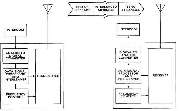
FREQUENCY HOPPING OPERATION
The same RF circuitry is used in both SC and FH. But in FH, the audio signal is converted into a digital data stream
prior to being transmitted. The data stream is interleaved (transmitted out of sequence). This spreads the signal
over several-frequency hops and reduces the degradation that could be caused by jamming. At the receive end,
the process is reversed. The data stream is recovered from the RF carrier. The data is deinterleaved and sent
through the digital-to-analog converter to recover the original audio.
When the RT is first keyed, a synchronizing signal is transmitted prior to the interleaved message. When the
receiving RT detects the synchronizing signal, it decodes it and adjusts its timing circuitry to synchronize with the
transmitting RT. When the transmitting RT is unkeyed, an end-of-message code is sent twice. This tells the
receiving RT to return to its passive receive or idle mode.
The RT is in the passive receive mode when it is not actively transmitting or receiving a message. During passive
receive, the RT searches for the synchronizing signal at the beginning of a transmission. The normal search
procedure allows the receiving RT clock to be off by ± 4 seconds and still sync with the transmitting RT. When the
1-12
|