|
| |
TM 11-5821-333-12
1-15. FH SYNC TIME.
The FH sync time feature of the RT is for FH operation. It is not a substitute for a wrist watch or a clock. There are
seven different clocks in the RT. There is a base clock and separate clocks for PRESET switch positions 1 through
6. When FH sync time is first loaded into the RT, either from a cold start or manually, all seven clocks are set to
the same time. When an ERF is received, that sender’s time is loaded into the preset along with the hopset. It
must be within one hour of the base clock.
The clock of an RT operating in an FH net must match the FH sync time within +4 seconds. Regular radio traffic
keeps the radio clocks synchronized. The FH sync time in any RT is updated every time a message is received.
The Net Control Station (NCS) is the time standard for the net. It is important for the NCS to be an active member
of the net. If you are a member of more than one net, you should communicate with the NCS of each net daily.
NOTE
An NCS operator may load FH sync time by using the keyboard. In this case, all clocks in the RT are
reset to the base clock. If the NCS is operating in more than one net, sync time for other channels is
obtained by ERF. It is not possible to reset the FH sync time for only one channel manually. This can
only be done using ERF.
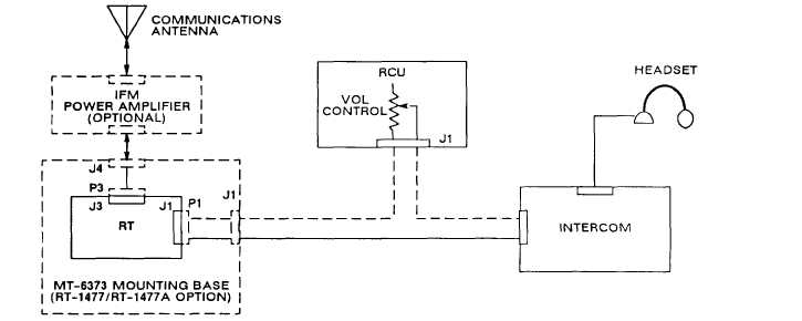
1-16. AUDIO SIGNAL PATHS.
The radio set transmits RF signals. The RF is radiated by the aircraft communications antenna. When the headset
push-to-talk (PTT) is pressed, an RF carrier in the RT is frequency modulated by audio from the headset and by a
150-Hz squelch tone. An optional power amplifier may be connected between RT and antenna.
PATHS OF AUDIO SIGNALS
Radio signals received at the antenna enter the RT at J3. The optional power amplifier passes receive signals
unchanged. The RT processes the FM signal and recovers the audio signal. The recovered audio signal is then
sent through system connector J1 to the aircraft intercom and headset. If a Remote Control Unit (RCU) is used,
the audio goes through the VOL control in the RCU, For the RT to operate in receive, the intercom PTT line must
be open (not ground). A 150-Hz squelch tone must be detected to break squelch when SQ ON (squelch on) and
SC (single channel) are selected on the RT or RCU. All FH (frequency hopping) operation is in squelch on, no
matter where the FUNCTION switch is set.
Radios that have data and communications security (COMSEC) capability will route audio signals through the
KY-58 or data rate adapter. (See paragraphs 1-18 and 1-20.)
1-11
|