 |
|||
|
|
|||
|
|
|||
| ||||||||||
|
|  TM
11-5820-919-40-1
by 200.
The 2,000,000 pulses will
plus 4.91 MHz is 6.91 MHz, and
29.9999 MHz plus 4.91 MHz is 34.90
be divided to 10,000 pulses, which
MHz .
corresponds to 10 kHz.
This will
match the 10-kHz Standard and the
Table 2-7 indicates that the pre-
5.
VCO tune voltage will remain
scaler will pulse at a 1:11 ratio
constant.
nine times and then pulse at a
1:10 ratio the remaining times
7.
The approximate VCO tune voltage
before it is reset.
The high
can be determined from the slope
frequency loop filter will send
formula
one reset pulse back to the
g
=
mP+b
prescaler for every 200 pulses
(see table 2-8, number of divi-
where
sions) it receives from the pre-
g = the VCO tune voltage
scaler.
This means that the pre-
scaler will pulse 1:11 nine times
m = 6.4/28.,000
. 2.29 X 1 0-4
and 1:10 191 times.
So, for the
first 2009 pulses which enter the
P=
frequency
kHz
=
15,184.3
prescaler, 200 pulses will reach
=
the high frequency loop filter.
b
+2.13v
This is repeated for the remainder
In this case, the
VCO
tune
voltage
of the 20,090,000 pulses (corre-
is +5.6v.
sponding to 20,090,0 kHz) until
2,000,000 pulses reach the high
8.
Since the VCO tune voltage is con-
frequency loop filter.
stant , the voltage controlled oscil-
lator will continue to oscillate
Table 2-8 indicates that the
6.
at 15,164.3 kHz, which is the LO
divide counter inside the high
frequency loop filter will divide
output .
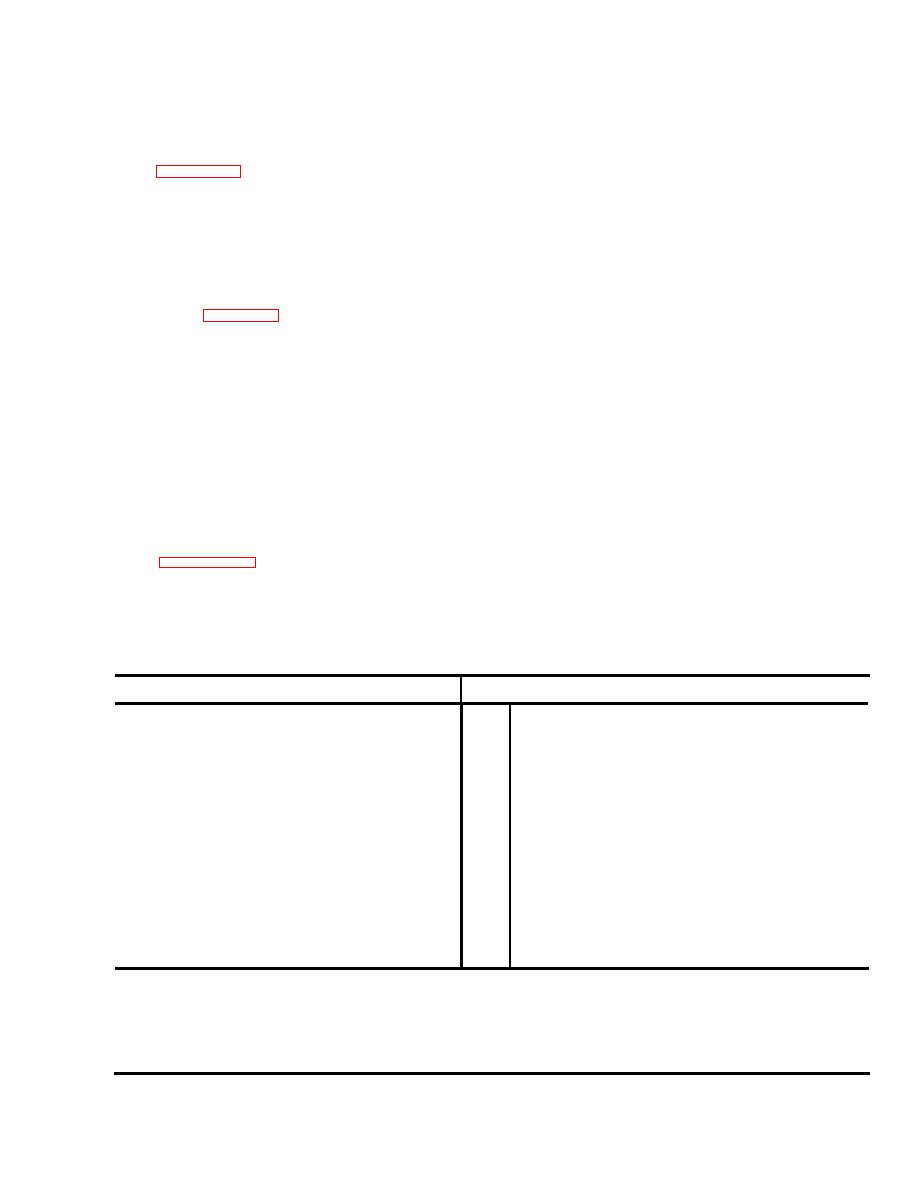
EQUATION SUMMARY
Formula
Pin
Component
P kHz + 75,000 kHz = a
VCO, U3, LO
34
1.
S6 (.1) kHz + S5 kHz + 90.0 kHz = b
Low
Frequency
29
2.
Phase Lock, U5
b kHz + 70,000 = C
Mixer
U6
1
3.
a kHz - C k H z = d k H z
19
4.
VCO,
U3,
mixer
= P MHz + 4.91 MHz
(d kHZ - (S4
+
1)
10
kHz)/10
Prescaler,
U4
39
5.
(S1 (100) + S2 (10) + S3) + 49
High Frequency Loop
Filter
U2,
6.
...
divide number
g = mP + b = VCO tune voltage
High Frequency Loop
Filter
U2,
18
7.
b = +2.13
VCO tune voltage
m = 2.29 X 1 0-4
Where
P is the control panel
S3
is
the
100-kHz digit (1)
frequency in kHz.
S4
is
the
10-kHz digit
(8)
S1 is the 10-MHZ digit
(1)
S5
is
the
1-kHz digit
(4)
S6
is
the
100-HZ, digit
S2 is the 1-MHz digit
(5)
(3)
|
|
Privacy Statement - Press Release - Copyright Information. - Contact Us |
