 |
|||
|
|
|||
|
Page Title:
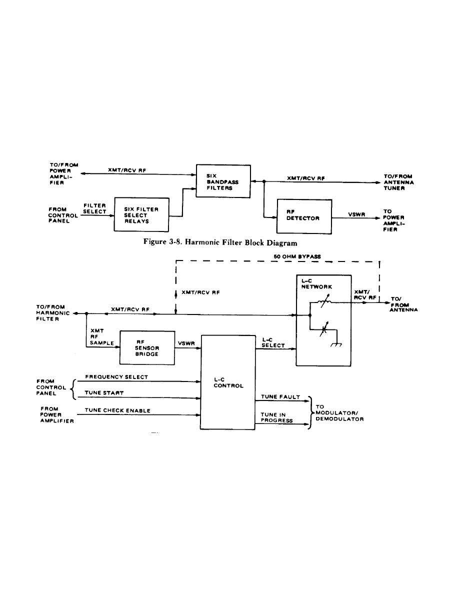
Figure 3-9. Antenna Tuner Block Diagram |
|
||
| ||||||||||
|
|  TM 11-5820-919-12
tuner automatically transforms the antenna impedance
3-36. HARMONIC FILTER (Figure 3-8). The harmonic
(reactive/resistive) to 50 ohms. This is done by using an
filter suppresses transmitter harmonics and noise levels
adjustable L-C network. The antenna tuner is normally
outside of the selected frequency band. To do this. the
off, and the L-C network is held in place by magnetic
Xmt/Rcv must pass through the bandpass and pass
latching relays. The antenna tuner becomes operational
filter. The Filter select signal, from the control pilot
whenever. (1) the radio is turned on, (2) the MODE
panel energizes one of the six filter select relays which
switch is changed from V-RCV to V-TR or D-RCV to D-
switches itches the associated filter into the circuit. The
TR, or (3) the frequency is changed. This causes a tune
filters are passive and are used in both transmitter and
start signal to he applied to the L-C control from the
receiver modes. The rf detector circuits monitor the
control panel.
amount of power point to and returning from the antenna
(vswr). The signal is applied to the power amplifier.
3-37. ANTENNA TUNER (Figure 3-9). The antenna
Figure 3-8. Harmonic Fiolter Block Diagram
Figure 3-9. Antenna Tuner Block Diagram
tune and perform a retune if necessary.
3-38. When a tune start is generated, the L-C control
resets the L-C network to zero. This means that there
will be no inductors or capacitors in the Xmt/Rev RF
pathway. When the operator transmits the rf sensor
3-39. If the tuning cycle takes too long (over 12
bridge samples the Xmt RF and produces a Wswr
seconds) the L-C control will output a Tune Fault signal.
signal. In addition, a Tune In Progress signal is sent to
This means that either the selected antenna is not within
the modulator/demodulator. The L-C control uses the
the tuning range of the antenna tuner, or that the
Vswr and the Frequency Select signals to adjust the L-C
module could be faulty . A Tune Fault signal is sent
network to its correct value via the L-C select signals. If
immediately y should a frequency below 2MHz be
a Tune Check Enable is routed from the power amplifier
during transmission, the antenna tuner will recheck its
3-11/(3-12 blank)
|
|
Privacy Statement - Press Release - Copyright Information. - Contact Us |
