 |
|||
|
|
|||
|
Page Title:
Section II. FUNCTIONAL OPERATION OF ELECTRONIC CIRCUITS |
|
||
| ||||||||||
|
|  TO 31R2-2GRC171-2
TM 11-5820-815-14
NAVELEX 0967-LP-544-5010
SECTION II
FUNCTIONAL OPERATION OF ELECTRONIC CIRCUITS
switches (S3 through S7) for remote frequency select
4-35.
GENERAL.
and two spst switches (S1 and S2) for remote power
on/off and squelch on/off of the receiver-transmitter. It
4-36. This section provides a detailed circuit descrip-
also contains a potentiometer (R1) for control of audio
tion of Radio Set Control C-7999/GRC-171 and of each
level from the receiver-transmitter and a ready lamp
module of Radio Receiver-TransmitterRT-980/GRC-
(DS1) that indicates the radio set is tuned and ready for
171. The description of each module includes a func-
use.
When off, the lamp indicates the receiver-
tional description that is supported by a block diagram
transmitter is in the process of tuning or that there has
and a detailed description of electronic circuits that is
been a circuit malfunction. The panel lights provide
supported by simplified schematic and complete
illumination for labeling on the front panel of the C-
schematic diagrams.
7999/GRC-171.
4-37. In this section reference is made to logic 0 and
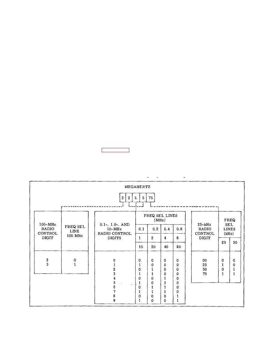
4-40. The frequency select switches develop bcd
logic 1 voltage levels. A logic 0 voltage level is defined
frequency select information in accordance with table 4-
as a voltage between 0 and +0.4 V dc. A logic 1 voltage
1. When applied to the 15-frequency select lines to the
level is defined as a voltage between +2.4 and +5.5 V dc.
receiver-transmitter, the bcd frequency select information
tunes the radio set to the frequency displayed on the
4-38.
RADIO SET CONTROL C-7999/GRC-171.
thumb-wheel switches. Diodes CR1 through CR15
provide isolation between the frequency select switches
of the C-7999/GRC-171 and the switches of the local
The C-7999/GRC-171 contains five thumb-wheel
frequency select located on the
Table 4-1. Radio Control Frequency Select Coding
4-7
|
|
Privacy Statement - Press Release - Copyright Information. - Contact Us |
