 |
|||
|
|
|||
|
Page Title:
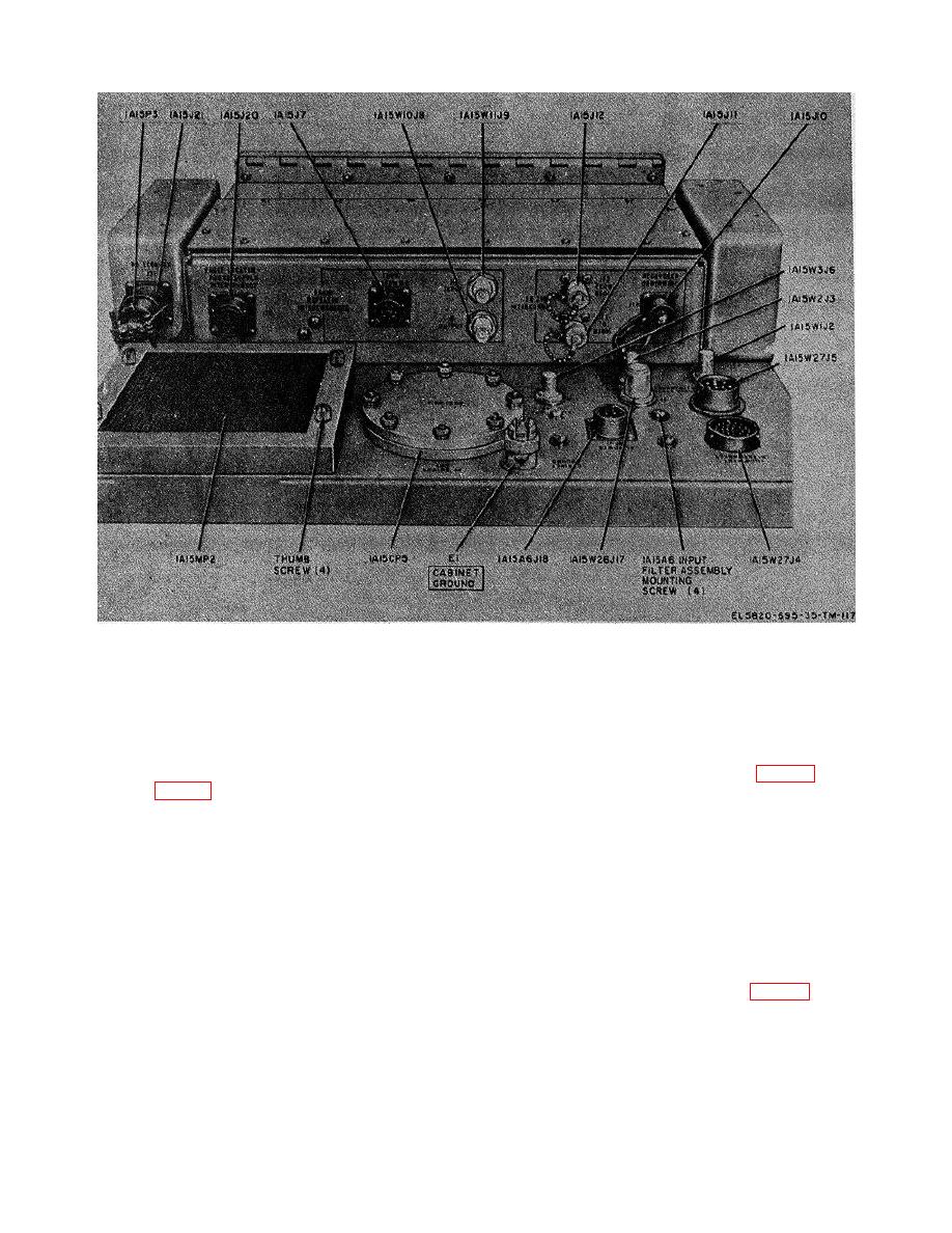
Figure 3-7. Transmitter, Radio T-1054/GRC-144, rear top view, parts location. |
|
||
| ||||||||||
|
|  TM 11-820-695-35
Figure 3-7. Transmitter, Radio T-1054/GRC-144, rear top view, parts location.
(9) Remove the two screws securing blank
(2) Loosen the two meter panel captive
panel 1A1A5 and, remove the blank panel.
screws (fig. 3-J1) on meter panel assembly 1A15A8.
(3) Position the meter panel assembly
upward and lock in position by use of the panel locking
b.
Removal of Rack Mounted Component
latch (fig. -4).
Connectors 1A1A13XA1 Through 1A1A13XA4 and
(4) Alternately unscrew each power supply
captive screw (fig. 3-1) one or two turns each until both
(1) Remove the ten screws and associated
captive screws rotate freely.
washers securing the rear shield to power supply chassis
(5) Slide power supply 1A1 out of electrical
assembly 1A1A13.
equipment cabinet 1A15 approximately 3 Inches by
(2) Tag and unsolder wires connected to
grasping the two power supply captive screws and 1A1
component terminals of the connector to be replaced.
bottom cover.
(3) Remove the two screws, two nuts, and
(6) Slide power supply 1A1 forward while
washers securing component connector to power supply
tilting downward to prevent damage to meter panel
chassis assembly 1A1A1 and remove the connector.
assembly 1A15A8 cables located above power supply
c. Replacement of Rack Mounted Component
1A1. Continue this removal technique until power
Connectors 1A1A3SXA1 Through 1A1A13XA4 and
supply 1A1 is completely removed from electrical
equipment cabinet 1A16.
(1)
Mount
replacement
component
(7) Loosen the two captive screws that
connector in place of removed connector using the two
secure 5/6v voltage regulator 1A1A1 to power supply
screws, two nuts, and washers removed in step b(3). Do
chassis assembly 1A1A13 and then remove 1A1A1 from
not tighten the two screws and nuts.
the chassis.
(8) Repeat step (7) for regulators 1A1A2,
1A1A3, 1A1A4, and 1A1A6 through 1A1A12.
3-38
|
|
Privacy Statement - Press Release - Copyright Information. - Contact Us |
