 |
|||
|
|
|||
|
Page Title:
Correlation Between Receive Operating Frequency and Electrical Frequency Synthesizer 2A14 RF Output Frequency |
|
||
| ||||||||||
|
|  TM 11-5820-695-35
to obtain a 70 MHz if signal containing received
intelligence.
The correlation between the receive
operating frequency and electrical frequency synthesizer
2A14 rf output frequency is described below.
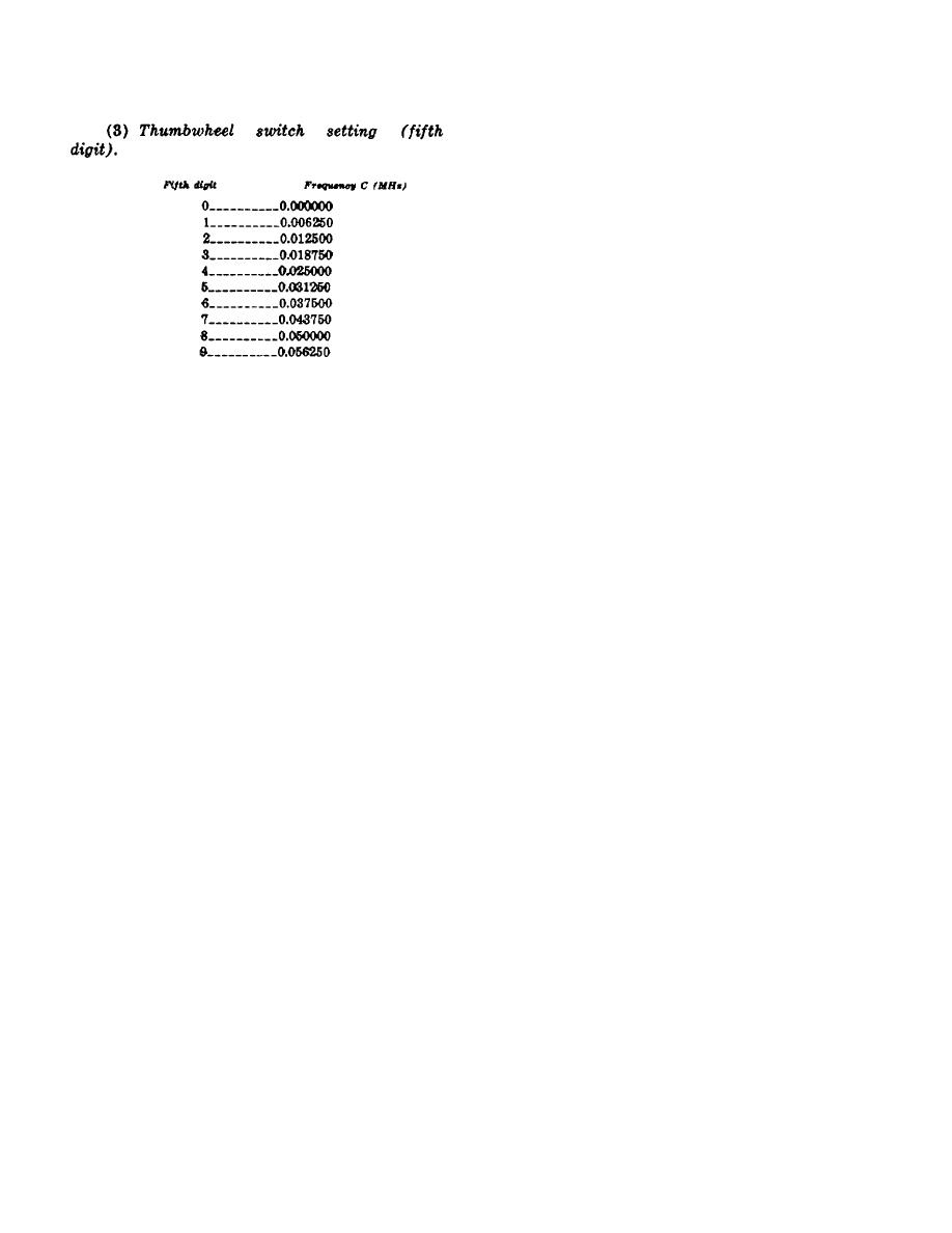
(1) When the thumbwheel switches on
2A14 are set to 4400.0 MHz (receive operating
frequency), the rf output frequency of 2A14 is 284.375
MHz. The 284.375 MHz signal is multiplied by 16 to
4550 MHz by the times 16 multiplier chain in Receiver,
Radio R-1467/GRC144. The 4560 MHz signal is then
mixed with a 220 MHz signal. Frequency selective
circuits in the R-1467/GRC-144 select the lower
sideband (4550 MHz minus 220 MHz) produced by the
mixing process to obtain a 4330 MHz local oscillator
signal. The 4330 MHz signal is then mixed with the
4400 MHz incoming signal (receive operating
frequency). Frequency selective circuits in the R-
c. Correlation Between Transmit Operating
1467/GRC-144 select the lower sideband (440 MHz
Frequency and Electrical Frequency Synthesizer 1A14
minus 4330 producing the required 70 MHz if. Signal
RF Output Frequency. The correlation between the
which contains the received intelligence.
transmit operating frequency and the electrical
(2) When the thumbwheel switches on 2A21
synthesizer 1A14 rf output frequency is described below.
are set to 4700.0 MHz (receive operating frequency),
(1) When the thumbwheel switches on
the rf output of electrical frequency synthesizer 2A14 is
1A14 are set to 4400.0 MHz (transmit operating
284.375 MHz. The 284.375 MHz signal is multiplied by
frequency), the rf output frequency of 1A14 is 284.375
16 to 4550 MHz by the times 16 multiplier chain in the
MHz. The 284.375 MHz signal is multiplied by 16 to a
R-1467/ GRC-144 and mixed with 220 MHz as
4550 MHz local oscillator signal by the times 16
described above. However, in order to obtain the
frequency multiplier chain in Transmitter, Radio T-
correct receiver local oscillator frequency (4770 MHz),
'1054/GRC-144. The 4650 MHz local oscillator signal is
frequency selective circuits select the upper sideband
then mixed with a 150 MHz frequency modulated signal
(4650 MHz plus 220 MHz). The 4770 MHz local
containing the integence to be transmitted. Frequency
oscillator frequency is then mixed with the 4700 MHz
selective circuits in the T-1054/GRC-144 select the
incoming signal (receive operating frequency).
lower sideband (4550 MHz minus 150 MHz) produced
Frequency selective circuits in the R-1467/GRC-144
by the mixing process to obtain the selected 4400 MHz
then select the lower sideband (4770 MHz minus 4700
(4.4 GHz) transmit operating frequency.
MHz) producing the required 70 MHz if signal which
(2) When the thumbwheel swtches on lA14
i
contains the received intelligence.
are set to 4700.0 MHz (transmit operating frequency),
e. Overall Block Diagram Description of Electrical
the rf output of 1A14 is 284.375 MHz. The 284.375
MHz signal is multiplied by 16 to a 4550 MHz local
signal flow (heavy lines on diagram) between plug-in
oscillator signal and mixed with 150 MHz as described
components (Al through A7) is shown. The dc power
above. However, to obtain the 4700 MHz (4.7 GHz)
distribution from power supply AS to components Al
transmit operating frequency, frequency selective
through A7 is also shown.
Each component is
circuits in the T-1054/GRC-144 select the upper
represented by a block on the diagram. Main chassis
sideband (4550 MHz plus 160 MHz).
circuits (e.g., thumbwheel switches) are also shown as
d. Correlation
Between
Receive
Operating
blocks on the diagram. The following subparagraphs
Frequency and Electrical Frequency Synthesizer 2A14
describe the main signal flow through electrical
RF Output Frequency. The thumbwheel switches on
frequency synthesizer 1A14.
The description also
electrical frequency synthesizer 2A14 are set to the
applies to electrical frequency synthesizer 2A14, except
desired receive operating frequency within the range of
the reference designations are prefixed with 1A14
4400.0 MHz to 5000.0 MHz.
The corresponding
instead of 2A14 and the word transmitter is used instead
electrical frequency synthesizer rf output frequencies
of receiver.
are the same as described in b above. The incoming
receive operating frequency is used as a mixing signal
2-33
|
|
Privacy Statement - Press Release - Copyright Information. - Contact Us |
