 |
|||
|
|
|||
|
Page Title:
To test IC amplifier 1 (IA1SA A5) |
|
||
| ||||||||||
|
| 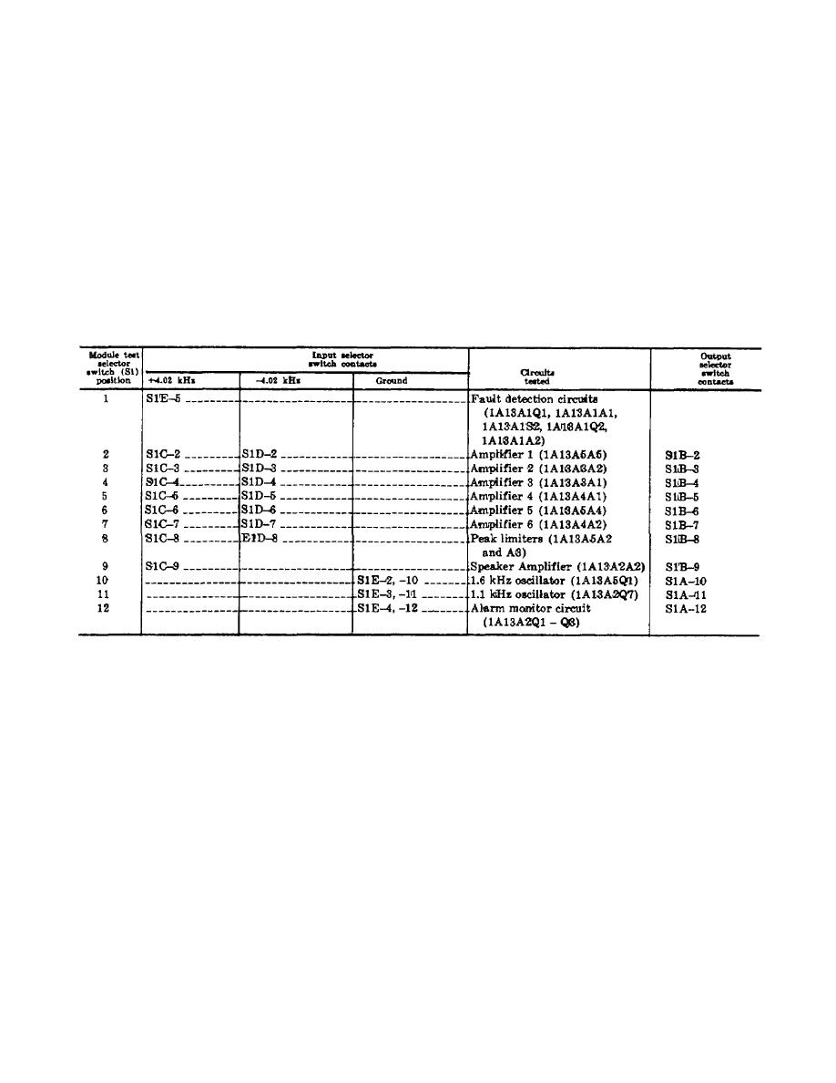 TM 11-6820-695-35
MODULE TEST press-to-test switch. If the output signal
grounds the 4.02 kHz monitor input thus removing its
level of amplifier 1 is normal, the lamp driver is biased
output voltage. This causes the lamp driver to be
off. Thus, the MODULE TEST indicator is extinguished
biased on and the MODULE TEST indicator conducts
indicating amplifier 1 is operating normally. However, if
and glows red.
the output signal level of amplifier 1 is low, the 4.02 kHz
c. To test IC amplifier 1 (IA1SA A5), the MODULE
monitor cannot develop a dc voltage sufficient to bias
TEST selector switch is set to position 2, connecting the
the lamp driver off. With the lamp driver biased on, the
4.02 kHz oscillator output signal through selector switch
MODULE TEST indicator lights red indicating that
contact S1C-2 to one input IC amplifier 1. This signal is
amplifier 1 is defective.
designated +4.02 kHz. The 4.02 kHz oscillator output
signal is also connected through transformer Ti. and
d. Amplifiers 2 through 6, the peak limiters, and
selector switch contact SID-2 to the output input of
the speaker amplifier are tested in the same manner as
amplifier 1. Transformer T1 reverses the phase of the
described above for amplifier 1. The selector switch
signal which is designated -4.02 kHz. The output signal
positions and input and output contacts associated with
level of amplifier 1' is applied to 4.02 kHz monitor Q2
each test are listed in the following chart.
through contact S18-2 of the selector switch and the
is set to position 11. Ground is applied to the oscillator
e. To test 1.6 kHz oscillator 1A13A5Q1, the
input through S1E-6 and SlE-11 causing the oscillator to
MODULE TEST selector switch is set to position 10
provide a 1.1 kHz tone output through IC amplifier
which connects ground to the oscillator input through
1Al1OA2A1. The 1.1' kHz tone signal is connected to
91E-2 and S1E-10.
With its input grounded the
the 1.1/1.6 kHz input of the 4.02 kHz monitor by the
oscillator starts to oscillate and provides 1.6 kHz tone
TEST TONE switch, emitter follower Q6 and IC
output through IC amplifier l'A13A5A1. The tone signal
amplifier A2 on board No. 2 lAr3&A2, and selector
is connected to the 1'.1/1.6 kHz input of 4.02 kHz
switch contact SlA-11.
monitor lA13AIQ2 through emitter follower Q5 and IC
amplifier A2 on 1A13A2, and contact SlA-10 of the
g. To test the central alarm monitor circuit on
selector switch. If the 1.6 kHz oscillator and emitter
meter panel assembly 1A15A8 and the monitor circuit
follower Q5 are operating normally (IC amplifier
on IA13A.2, the MODULE TEST selector switch S1 is
1A13A2A2 was tested for normal operation in position 9
set to position 12. Sections SlE and SIE-12 apply
of the selector switch), the MODULE TEST indicator
ground to simulate power amplifier alarm input OR
should be extinguished. If the 'l.6 kHz oscillator and/or
gates A and B on
emitter follower Q5 are not operating normally, the
MODULE TEST indicator will light red.
f. The 1.1 kHz oscillator lA'13A2Q7 is tested in a
manner similar to that described above for the 1.6 kHz
oscillator except that the MODULE TEST selector switch
2-26
|
|
Privacy Statement - Press Release - Copyright Information. - Contact Us |
