 |
|||
|
|
|||
|
|
|||
| ||||||||||
|
|  TM 11-5820-695-35
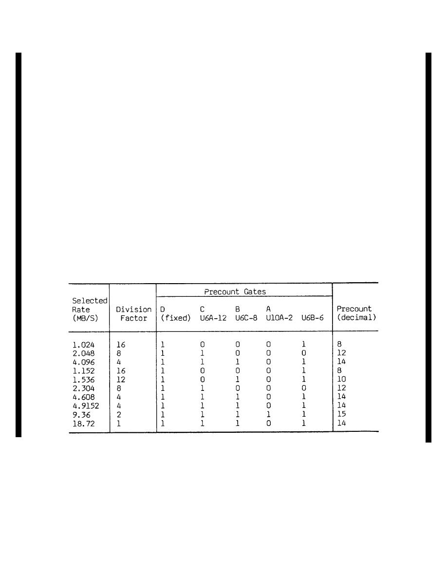
in the chart for rate 1.024. The precount is 8. This
apply the voltage for the logic 1 state to the rate select
means that U5 starts each count cycle (for rate 1.024) at
logic gates. The chart shows the crystal selected for
a count of 8 (binary 1000) and it reaches full count
each rate and the corresponding division factor. The
(binary 1111) 7 counts later. Each time the count
last four columns of the chart show the output logic
reaches binary 1111, U5 produces a positive pulse (RC)
states of the final crystal select gates. Operation of the
at pin 15. The duration of this pulse is one cycle of the
crystal select logic for rate 1.024 is typical. When
CLK input at U5-2 from U19. The signal at UiOD-8 is
1A12S4 is set for this rate, the signal at P1-B and at
then logic 0. On the eighth clock pulse, the logic 0 from
U7A-1 is logic 0. The signals from lA12S4 at all other
UlOD-8 resets U5 at pin 9. This injects the precount
inputs are logic 1. Logic 1 from U7A-6 is inverted by
again for the start of the next count cycle. Thus, for rate
U2A and the logic 0 at U2A-2 selects crystal Y1 as
1.024, a precount of 8 is stored in U5, and an output
discussed in (1) above. Operation of the crystal select
pulse at U5-15 is produced for every 8 cycles of the CLK
logic for any other rate or crystal is similar.
signal at U5-2. The signal from U5-15 is gated through
(6) The rate select signals at gates U6 and
U11C in synchronism with the oscillator signal from U-
U1O determine the division factor that will be used and
19 by the signal at U1OC-6. Divider U15 divides the
thus the data rate (clock) signal. The division factor for
signal from U5 by 2. Thus the oscillator signal has been
each rate is given in the chart below along with the logic
divided by 8 in U5 and by 2 in U15. So it has been
states of the signals at the precount inputs at US.
divided by 16 as indicated in the chart for rate 1.024.
These inputs in D, C, B, A order are the binary code for
Operation of the division factor select circuits and
the precount given in decimal form in the last column.
US/U15 is similar for any other data rate. The data rate
When data rate 1.024 is selected, the signals at U6-11
(clock) signal is gated through U14 which is a dual, 2-
and -13 are logic 0 and at U6-1, -2, -3, -4, -5 and -10 are
pole electronic switch. For all data rates from 1.024 to
logic 1. The signal at U1O-1 is logic 1. U10-2 and U6-
9.36, the signal from U15-5 at U14-10 is connected
6, -8 and -12 then apply precount inputs at U5 as shown
DIVISION FACTOR CHART
Change 6 2-24.5
|
|
Privacy Statement - Press Release - Copyright Information. - Contact Us |
