 |
|||
|
|
|||
|
|
|||
| ||||||||||
|
|  TM 11-5820-670-30
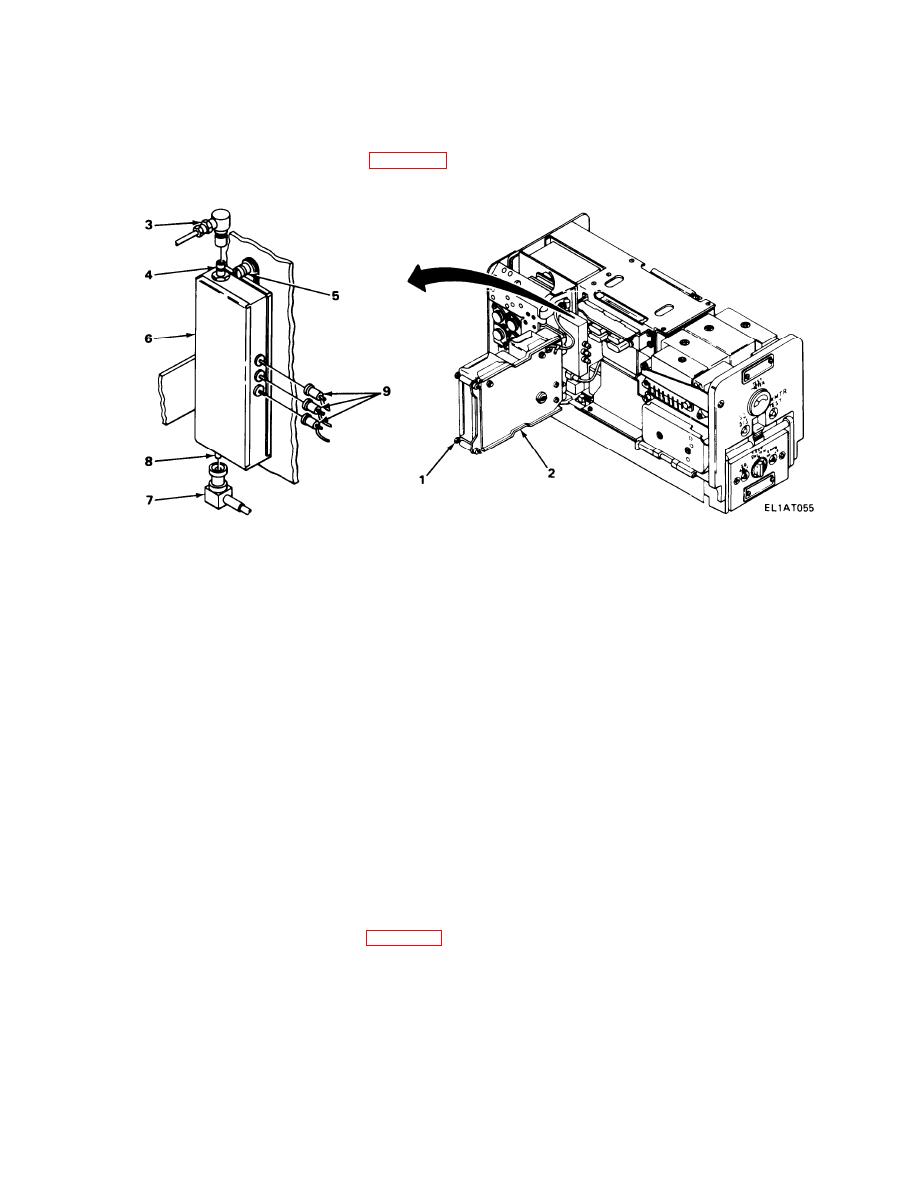
2-61. A4900 ASSEMBLY REPLACEMENT.
MATERIALS/PARTS: Attenuator, variable, A4900 (P/N SME619695)
PRELIMINARY PROCEDURE: Remove case (para 2-39).
REMOVAL
1. Using screwdriver, loosen two captive screws (1) and swing out A4000 assembly (2).
2. Disconnect blue wire (P4902) (3) from J4902 (4).
3. Using screwdriver, loosen two captive screws (5) and move A4900 assembly (6) away from
chassis.
4. Disconnect blue wire (P4901) (7) from J4901 (8).
5. Disconnect three color-coded wire plugs (9).
6. Remove A4900 assembly (6).
INSTALLATION
1. Connect three color-coded wire plugs (9).
2. Connect blue wire (P4901) (7) to J4901 (8).
3. Position A4900 assembly (6) in chassis and, using screwdriver, tighten two captive
screws (5).
4. Connect blue wire (P4902) (3) to J4902 (4).
5. Close A4000 assembly (2) and, using screwdriver, tighten two captive screws (1).
FOLLOW-ON MAINTENANCE: Install case (para 2-39).
2-202
|
|
Privacy Statement - Press Release - Copyright Information. - Contact Us |
