 |
|||
|
|
|||
|
|
|||
| ||||||||||
|
|  TM 11-5820-670-30
2-31. CARRIER SQUELCH ADJUSTMENT. (CONT)
ADJUSTMENT PROCEDURE
1. On TS-2575/ARC-131, place the +28 VDC ON OFF switch to ON.
EL1AT239
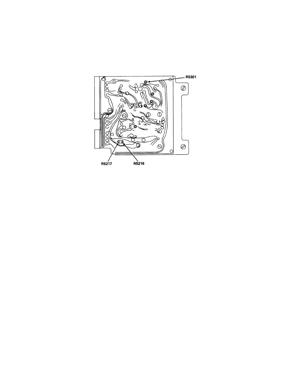
Set carrier squelch potentiometer R5216 on A5500 assembly fully clockwise.
2.
Set RT-823/ARC-131 SQ ADJ control fully clockwise.
3.
Set control unit mode switch to T/R. VOL control fully clockwise, SQUELCH switch to DIS,
4.
and frequency selectors to 60.05 MHz.
5.
Set AN/URM-127 amplitude control to 0 and adjust output frequency to 1000 Hz.
Set AN/URM-103 FUNCTION selector switch to EXT MOD and adjust output for 10 microvolt.
6.
7.
Adjust AN/URM-127 for 8 kHz deviation as indicated on AN/URM-103 meter.
Set TS-723A/U function switch to METER and tune AN/URM-103 frequency to 60.05 MHz as
8.
indicated by maximum indication on TS-723A/U meter.
Set control unit SQUELCH switch to CARR.
9.
Reduce AN/URM-103 rf output to minimum, then slowly increase output to a point where
10.
squelch just breaks.
If receiver-transmitter breaks squelch at an input of more than 0.7 microvolt, rotate
11.
R5216 on A5500 assembly counterclockwise so that squelch breaks at 0.55 microvolt.
Remove AN/URM-103 input to receiver-transmitter, rotate SQ ADJ control fully counter-
12.
clockwise, and ensure unit is unsquelched.
Rotate SQ ADJ control clockwise until receiver-transmitter just squelches.
13.
2-135
|
|
Privacy Statement - Press Release - Copyright Information. - Contact Us |
