 |
|||
|
|
|||
|
Page Title:
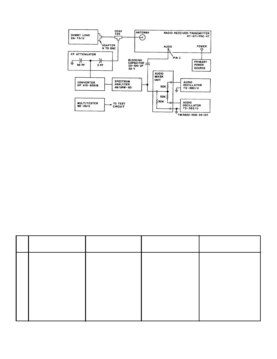
Figure 5-3 Transmitter Spurious Outputs Adjustment. Equipment Setup |
|
||
| ||||||||||
|
|  TM 11-5820-509-35
Figure 5-3 Transmitter Spurious Outputs Adjustment. Equipment Setup
for more than a few seconds at a time in the
c. Procedure.
unloaded condition, serious equipment
(1) On
RT-671/PRC-47,
set
the
damage can result.
KILOCYCLES indicator to 2400; place the CW-
FSK/VOICE switch to VOICE, the XMTR PWR switch to
LO, and the OPR-TUNE switch to OPR.
(3) After resonating the power amplifier plate
circuit at the LO setting of XMTR PWR switch, place the
(2) Place the turns-counters of POWER
XMTR PWR switch to HI and repeat the peaking
AMPLIFIER TUNE and POWER AMPLIFIER LOAD
procedure.
controls to the settings recommended on the LOAD-
TUNE chart on the front of the receiver-transmitter.
(4) Return the OPR-TUNE switch to OPR.
(5) Adjust the spectrum analyzer to 2400
CAUTION
kHz; set the audio oscillators to 900 Hz and 2800 Hz
Before making the following measurements
respectively at an output level of 0.1 volts per tone.
and adjustments, resonate the POWER
AMPLIFIER TUNE and POWER AMPLIFIER
NOTE
LOAD controls on the front of the receiver-
Adjust the driver bias between-30 and -55
transmitter for maximum deflection on the
volts dc and the power amplifier grid bias
XMTR OUTPUT meter. Use the OPR-TUNE
between-105 and - -1 1 5 volts dc to obtain the
switch to control power amplifier plate power.
minimum distortion products.
Do not permit the power amplifier to operate
Test
Radio
equipment
control
Test
Performance
Step
settings
settings
procedures
standards
1
Place CW-FSK/VOICE switch to CW-FSK. Measure third-order
Not less than 30 dB down
Switch to CW-FSK
distortion product above
from peak envelope power
the passband (above
output level.
2404.6 kHz).
2
Same as step 1.
Measure third-order
Same as step 1.
distortion product below
the passband (below
2399.0 kHz).
3
Reduce output of 900-Hz
Same as step 1.
Measure carrier amplitude
Not less than 40 dB down
Oscillator to zero.
(2400.0 kHz).
from peak envelope power
output level.
4
Same as step 3.
Same as step 1.
Measure amplitude of 2800
Not less than 60 dB down
Hz sideband that occurs
from peak envelope power
below the carrier (2397.2
output level.
kHz).
5-5
|
|
Privacy Statement - Press Release - Copyright Information. - Contact Us |
