 |
|||
|
|
|||
|
Page Title:
Mechanical Alignment of CV-1377A/PRC-47 STUB Rack Coupler |
|
||
| ||||||||||
|
| 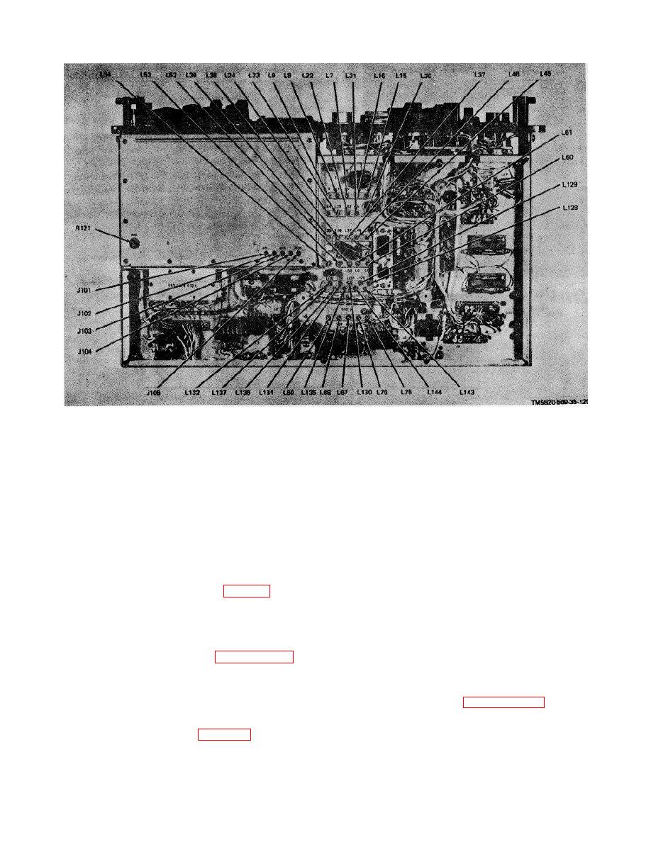 TM 11-5820-509-35
Figure 3-105. Radio Receiver-Transmitter RT-671/PRC-47 ((A8) ),Bottom View, Location of Test Points and
Adjustments.
3-21. Mechanical Alignment of CV-1377A/PRC-47
(4) Set the front panel controls of TR-
STUB Rack Coupler
671/PRC-47 as follows:
NOTE
(a) POWER-LIGHTS switch to POWER
Perform this check only when one or
ON.
more of the following conditions
(b} KILOCYCLES indicator to 2000.
(c) CW-
exist:
The
RT-6171
/PRC-47
FSK/VOICE switch to VOICE. (d) OPR-TUNE switch to
frequency selection mechanism has
OPR.
been disassembled for repair; when
(5) Loosen the setscrew that clamps the shaft
the CV-1377A/PRC-47 plug-in module
collar to the slug rack coupling half and slide the
has been replaced.
coupling half along the axis of the drive shaft until
a. Test Procedures.
Measure the clearance
specification clearance is obtained.
between halfs of the slug rack coupler (fig. 3-96) with a
NOTE
feeler gage. Clearance must be 0.002- to 0.020-inches.
Recheck the voltmeter readings during
If not, adjust in accordance with step b.
steps (5) and /6) to assure that the slugrack shaft is
b. Adjustment Procedures.
not rotated during this adjustment.
(1) Remove the RT-671/PRC-47 from its
(6) Retighten the shaft collar setscrew tightly.
case using the procedures detailed in paragraph 3-11.
(7) Place
POWER-LIGHTS
switch
to
(2) Connect the primary power source to the
POWER OFF and disconnect the multimeter.
POWER connector on the front panel of RT-671 //PRC-
(8) Return the RT 671/PRC-47 to its case
47.
using the procedures of paragraph 3-11 if no further
(3) Connect the dc test probe of Multimeter
adjustments are required.
ME-26A/U alternately to test jacks A7J5 and A7J6 of
Oscillator Control C-311/PRC 47 (fig. 3-100).
3-124
|
|
Privacy Statement - Press Release - Copyright Information. - Contact Us |
