 |
|||
|
|
|||
|
Page Title:
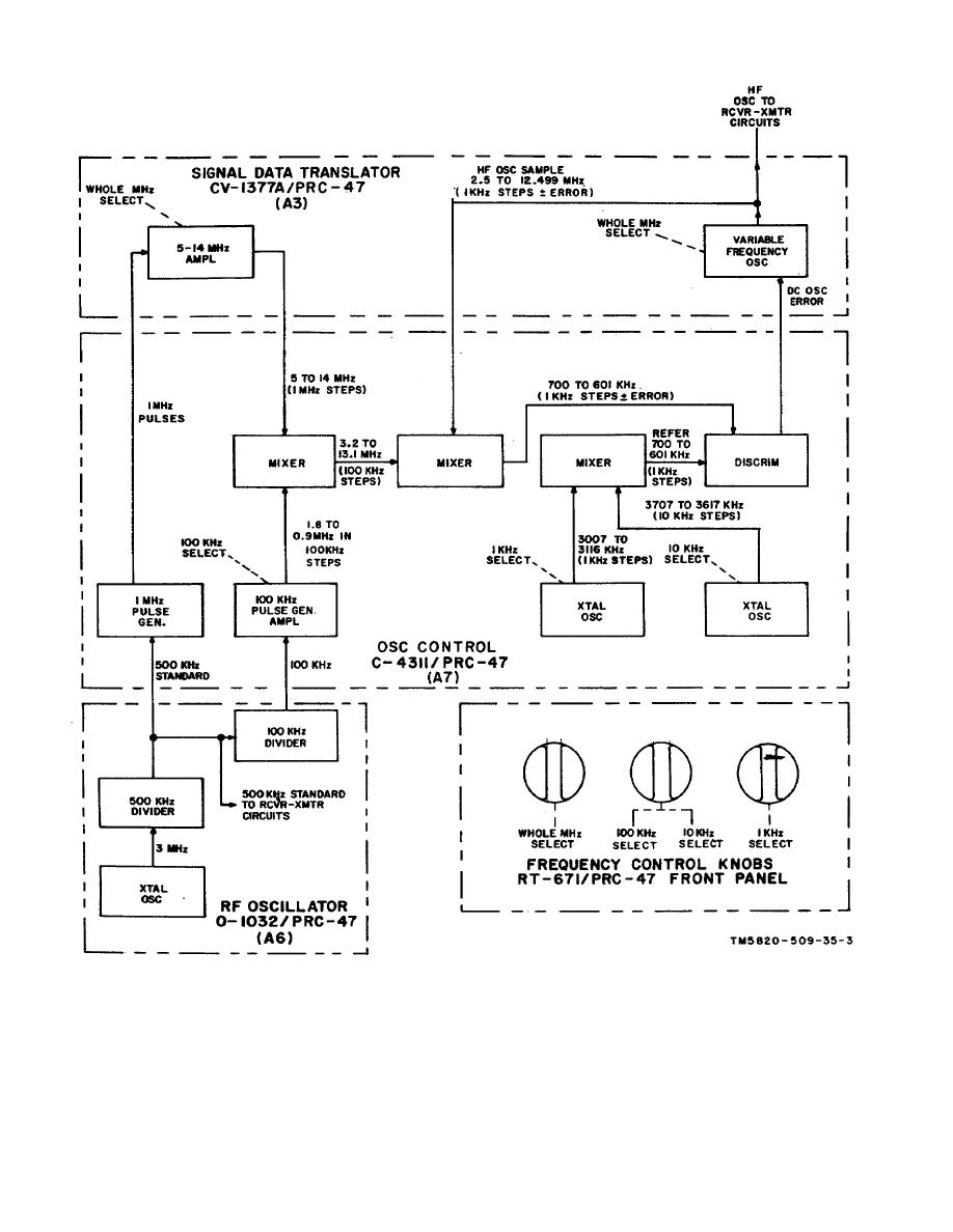
Figure 2-3. Frequency Control circuits, Block Diagram |
|
||
| ||||||||||
|
|  TM 11-5820-509-35
Figure 2-3. Frequency Control circuits, Block Diagram
A7. The 1-MHz pulse generator of this module doubles
a sine wave output at the 1-MHz frequency step that has
the incoming 500-kHz standard signal and then converts
been selected by the frequency control knobs on the
front panel. The 100-kHz output of the divider in radio
the resulting signal into a 1-MHz pulse-train. These
pulses are applied to the 5 to 14-MHz amplifier circuits
frequency oscillator (A6) is applied to the 100-kHz pulse
of the CV1377A/PRC-47 (A3) where a ringer generates
2-6
|
|
Privacy Statement - Press Release - Copyright Information. - Contact Us |
