 |
|||
|
|
|||
|
Page Title:
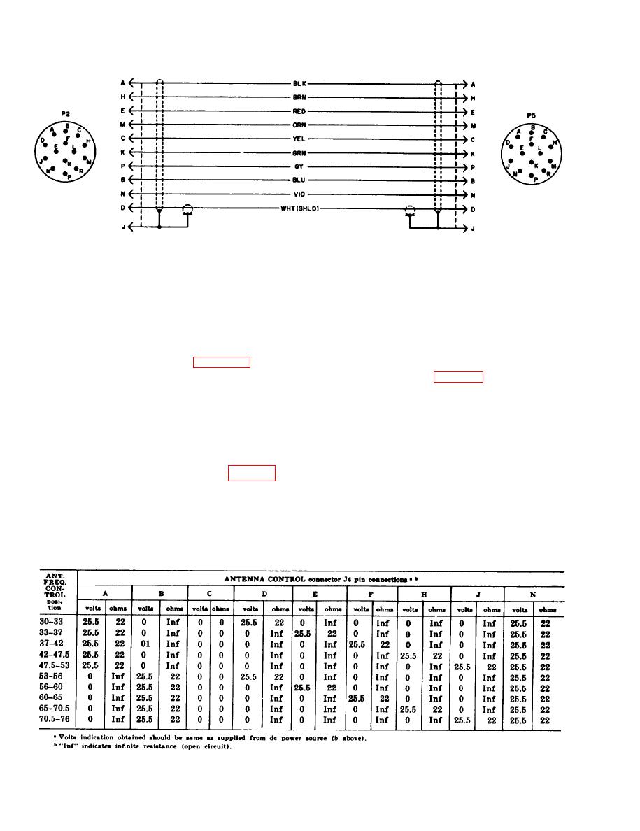
Continuity and Short Circuit Tests for Cable Assembly, Special Purpose, Electrical CX-4655/GRC |
|
||
| ||||||||||
|
|  TM 11-5820-498-35
NOTE:
TM5020-498-35-6
CONNECTORS VIEWED FROM PIN SIDE.
Figure 3-5. Cable Assembly, Special Purpose, Electrical CX-4655/GRC, wiring diagram.
3-7.
Continuity and Short Circuit Tests for
switch settings and resistance indications. Refer to
c below for the resistance indications at all switch
Cable Assembly, Special Purpose, Elec-
positions of the ANT. FREQ. CONTROL switch.
trical CX-4655/GRC
Use Multimeter ME-26(*)/U as an ohmmeter to
b. Voltage Measurements. To make voltage
c h e c k for continuity and short circuits in
measurements, apply a 25.5-volt dc power source
CX-4655/GRC wires. Refer to figure 35 for the
(or 25.2 volts from the PP-2953(*)/U)to POWER
wiring diagram.
INPUT connector J3 (para 3-4). Refer to figure
3-6 for the required AM2060(*)/GRC switch set-
3-3. AM-2060(*)/GRC, Voltage and
tings and voltage indications. Refer to c below for
Resistance Measurements at Connectors
the voltage indications at all positions of the ANT
J2, J3, and J4
FREQ. CONTROL switch.
To isolate trouble to a defective part in the
c. ANTENNA CONTROL Connector J4. Voltage
AM-2060(*)/GRC, other than on the plug-in as-
(b above) and resistance (a above) indications at
sembly, use the techniques given in a through c
connector J4 for all positions of ANT. FRE-
below. Use the schematic diagram (fig. 4-9) to
QUENCY CONTROL switch are provided in the
trace and isolate the defective part.
following chart. The SPKR switch is set to OFF;
the PWR switch is set to ON. The ME-26(*)/U
sistance measurements, remove all power and
cable connections to the AM-2060()/GRC. Refer
measurements are made between J4 pins and
to figure 3-6 for the required AM-2060(*)/GRC
ground.
3-8
|
|
Privacy Statement - Press Release - Copyright Information. - Contact Us |
