 |
|||
|
|
|||
|
Page Title:
Microphone Amplifier Assembly A80, Circuit Functioning |
|
||
| ||||||||||
|
|  TM
11-5820-401-35-1/NAVELEX
0967-432-3020
minal T of W701J702, through W701S702, to
microphone output of the audio accessory has
erminal S of W701S701. An operator can listen
been amplified in microphone amplifier A80 (para
to either of the channels being used for retrans-
33), it is applied through switch W701S701 and
mission but cannot key either transmitter. How-
terminal U of connector W701J701 to the trans-
ever, he can modulate the keyed transmitter de-
mitting circuits of the receiver-transmitter.
pending on the position of RAD TRANS switch
(2) When RAD TRANS switch W701S701
W701S701. Similarly, when the C-2299/VRC is
is at position 2, muted audio from the second re-
connected to the AM-1780/VRC (fig. 3-1), crew-
ceiver-transmitter is fed from terminal J of
members cannot key the recei ver-transmitters be-
W701J702 through the same circuit as given in
cause the INSTALLATION switch on the AM-
(1) above. The audio accessory will control the
1780/VRC is set to RETRANS position which
second receiver-transmitter connected to W701-
opens the keying control lines.
J702 through the same circuits described in (1)
above.
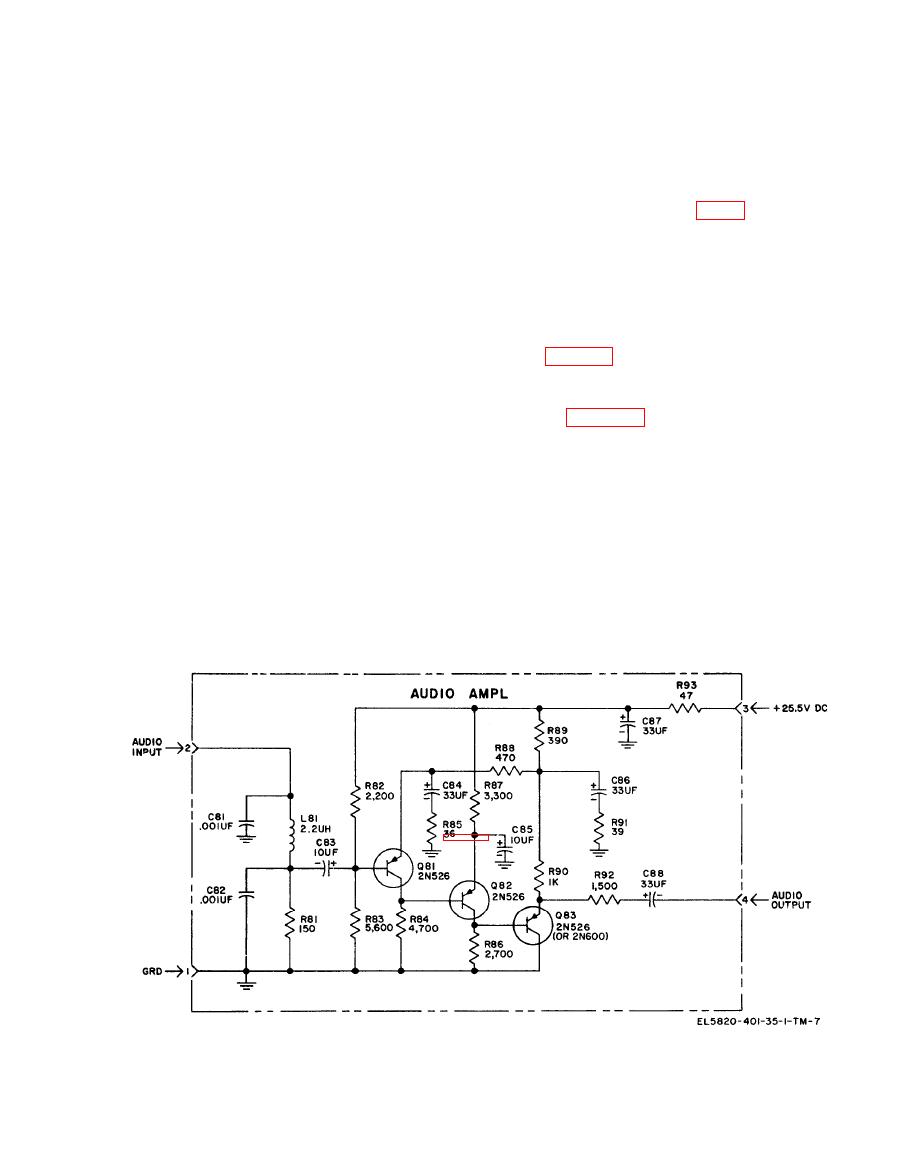
3-3. Microphone Amplifier Assembly A80,
b. When RETRANS switch W701S702 is in
Circuit Functioning
ON position, the monitor amplifier output of the
first receiver-transmitter is fed to the microphone
Microphone amplifier assembly A80 is a three-
line of the second receiver-transmitter from ter-
stage, direct-coupled amplifier used in the C-
minal K of W701J701 and terminal U of con-
2299/VRC (fig. 32) and also in control boxes of
nector W701J702. Similarly, the monitor ampli-
Intercommunication Set AN/VIC-l (V) (TM 11-
fier output of the second receiver-transmitter is
583034012): C-2296/VRC, C-2297/VRC, and
fed to the microphone line of the first receiver-
C-2298/VRC. The A80 receives its input signal
transmitter from terminal K of W701J702 to ter-
from the dynamic microphone connected to the
minal U of W701J701. When a keying signal is
control box. Its output is fed to the speech ampli-
received (by operation of squelch and retransmit
fier of the receiver-transmitters or to the inter-
relays) by the first receiver-transmitter, the sec-
phone amplifier of the AM-1780/VRC.
ond receiver-transmitter will be keyed through a
a. The input from the dynamic microphone is
circuit from terminal T of W701J701 through
fed through an RF filter network composed of
W701S702, to terminals S of W701J702. Sim-
capacitors C81 and C82 and inductor L81;
ilarly, when a keying signal is received by the
through impedance-matching resistor R81 and
second receiver-transmitter, the first receiver-
coupling capacitor C83 to the base of transistor
transmitter is keyed through a circuit from ter-
I
|
|
Privacy Statement - Press Release - Copyright Information. - Contact Us |
